![[Home]](http://www.bayleshanks.com/cartoonbayle.png)
In this part we'll focus on instruction sets, addressing modes, etc, rather than on other aspects of processors such as pipelining.
Close to machine language (bung a 20-bit address, but by using a 16-bit address and 4-bit index. This is the root of the 64k segment size problem that dogs DOS to this day.
Since DOS only ran in 8086 mode there was no easy way to address more than one meg of memory, and various standards were set up to allow access to addresses beyond the 1 meg barrier. The bug in the '286 was useful in that it allowed 8086 mode programs to see the first 64k above 1 meg. It involved some weird messing about with the keyboard controller to toggle the state of the 21st address line, and this is why you still see on some syt not exactly; most assembly languages allow the programmer to define alphanumeric labels for code positions and alphanumeric variable names) Linear imperative sequence of opcodes; statements, not expressions No assignment operator to assign to a variable; the 'alphanumeric variable names' mentioned above just map to a single memory location Registers or stack separate from memory Condition flags Untyped Goto and bne style control flow Addressing modes at least 3: immediate, register (or memory), indirect (tho see Parallax Propeller which uses self-modifying code in lieu of indirect) operations on fixed width data (e.g. "assume these memory locations contain 8-bit ints and add them" or "assume these memory locations contain 32-bit floats and add them") sometimes macros: for generating inline, as opposed to called, subroutines
For more inspiration about the sorts of instructions that might go into a VM, one might look at popular CPU instruction sets.
My purpose in including this section is NOT to teach the reader the basics of assembly language and computer architecture; i assume that the reader already knows that. I just want to give you more food for thought about 'minimal' programming languages.
Links:
the winner was: general purpose registers
From http://www.cl.cam.ac.uk/teaching/0405/CompArch/mynotes.pdf :
Classic RISC Addressing Modes:
Less RISCy addr modes (ARM and PowerPC?):
CISC Addressing Modes:
Links:
regularity vs code density:
http://www.strchr.com/x86_machine_code_statistics
distribution by instruction length: 1 4.77% 2 17.67% 3 18.72% 4 12.28% 5 13.78% 6 15.60% 7 13.30% 8 2.46% 9 0.01% 10 1.02% 11 0.41%
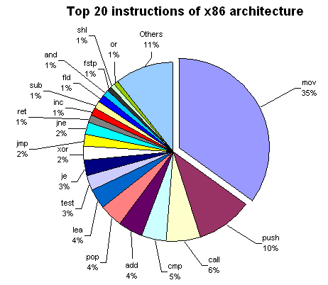
top 20 instructions: mov 35% push 9.99941228328% call 6.01175433441% cmp 4.62415515721% add 4.31295915369% pop 4.08257419924% lea 3.85953570379% test 2.79400528945% je 2.74316779312% xor 2.44255069057% jmp 2.22421392889% jne 2.19541580958% ret 1.45224801646% inc 1.36320893329% sub 1.32677049662% fld 1.29180135175% and 1.10843373494% fstp 1.03967087864% shl 0.84748751102% or 0.738172200999% Others 10.5436379665%
number of operands: 0 3% 1 37% 2 60%
addressing modes: immediate 20% register 56% absolute address 1% indirect address 23%
instruction formats (note the destination comes first in the following): register-memory 35.4% register-register 26.5% register-immediate 16% memory-register 15.2% memory-immediate 6.8%
" The most popular instruction is MOV (35% of all instructions). Note that PUSH is twice more common than POP. These instructions are used in pairs for preserving EBP, ESI, EDI, and EDX registers across function calls, and PUSH is also used for passing arguments to functions; that's why it is more frequent. CALLs to functions are also very popular.
More than 50% of all code is dedicated to moving things between registers and memory (MOV), passing arguments, saving registers (PUSH, POP), and calling functions (CALL). Only 4th instruction (CMP) and the following ones (ADD, LEA, TEST, XOR) do actual calculations.
From conditional jumps, JE and JNE (equal and not equal) are the most popular. CMP and TEST are commonly used to check conditions. The percentage of the LEA instruction is surprisingly high, because MS VC++ compiler generates it for multiplications by constant (e.g., LEA eax, [eax*4+eax]) and for additions and subtractions when the result should be saved to another register, e.g.:
LEA eax, [ecx+04] LEA eax, [ecx+ecx]
The compiler also pads the code with harmless forms of LEA (for example, the padding may be LEA edi, [edi]). As is easy to see, the top 20 instructions include all logical operations (AND, XOR, OR) except NOT.
Though LAME encoder uses MMX technology instructions, their share in the whole code of the program is very low. Two FPU instructions (FLD and FSTP) appears in the top 20.
But what about other instructions? It turns out that multiplication and division are very rare: IMUL takes 0.13%, IDIV takes 0.04%, and both MUL and DIV do 0.02%. Even string operations such as REPZ SCASB or REPZ MOVSB are more common (0.32%) than all IMULs and IDIVs. On the contrary, FMUL is more common than FADD (0.71% versus 0.27%). "
Table 3:Most used x86 instructions...in DOS application
mov reg reg shl push add inc pop jz les shl 2 arg mov reg mem mov reg mem
Rank instruction # of MOP execution frequency 1 mov r16 r16 1 12.5% 2 shl r16 1 6.8% 3 push r16 2 5.1% 4 add r16 r16 1 5.1% 5 inc r16 1 4.1% 6 pop r16 2 4.0% 7 jz i8 1 3.6% 8 les r16 m16d8 4 3.3% 9 shl r16 i8 1 3.0% 10 mov r16 m16d0 1 2.9% 11 mov r16 m16d8 1 2.7% 12 jge i8 1 2.0% 13 wait 1 1.8% 14 cmp m16d16 i8 2 1.7% 15 jnz i8 1 1.6% 16 dec r16 1 1.5% 17 jmpn i8 1 1.5% 18 cmp m16d16 r16 2 1.5% 19 jl i8 1 1.3% 20 calln i16 ? 1.3% 21 mov r16 i16 1 1.2% 22 mov r8 r8 1 1.1% 23 mov r16 m16d16 1 1.1% 24 jle i8 1 1.0% 25 or r16 r16 1 1.0% 26 cmp r16 m16d8 2 1.0% 27 mov m16d0 r16 1 0.9% 28 mov r8 m8d0 1 0.9% 29 retn ? 0.8% 30 push m16d8 3 0.7% 31 cmp r16 m16d0 2 0.7% 32 jae i8 1 0.7% 33 cmp r16 i8 1 0.7% 34 stosb 2 0.6% 35 mov m16d8 r16 1 0.6% 36 scasb 3 0.6% 37 mov m16d16 r16 1 0.6% 38 movsw 4 0.6% 39 sub r16 r16 1 0.6% 40 movsb 4 0.6% 41 cmp m8d0 i8 2 0.5% 42 retf ? 0.5% 43 jb i8 1 0.5% 44 xchg r16 r16 1 0.4% 45 xor r16 r16 1 0.4% 46 add r16 i8 1 0.4% 47 clc 1 0.3% 48 cmp r8 m8d0 2 0.3% 49 jmpn i16 1 0.3% 50 jg i8 1 0.3% 51 cmp i16 r16 1 0.3% 52 stosw 2 0.3% 53 loop i8 2 0.3% 54 imul r16 r16 i16 1 0.3% 55 cmp m16d0 i8 2 0.3% 56 add r16 m16d8 2 0.3% 57 cmp r16 m16d16 2 0.3% 58 or r8 r8 1 0.3% 59 imul r16 r16 i8 1 0.3% 60 les r16 m16d0 4 0.3% 61 mov m8d0 r8 1 0.3% 62 fld m32d0 3 0.3% 63 xor r16 m16d16 2 0.2% 64 cmp r8 i8 1 0.2% 65 leave 3 0.2%
TOTAL 90.8%
Table 4: Most used x86 instructions...in Windows95 applications
push mov reg mem jz pop mov reg reg inc mov reg mem xor jnz calln
Rank instruction # of MOP execution frequency 1 push r32 2 8.4% 2 mov r32 m32d8 1 7.1% 3 jz i8 1 5.7% 4 pop r32 1 4.2% 5 mov r32 r32 1 4.0% 6 inc r32 1 3.0% 7 mov r32 m32d0 1 2.9% 8 xor r32 r32 1 2.7% 9 jnz i8 1 2.7% 10 calln i32 ? 2.2% 11 cmp r32 r32 1 2.2% 12 mov r16 m16d8 1 2.1% 13 test r32 r32 1 2.1% 14 retn i32 ? 1.9% 15 jl i8 1 1.9% 16 mov r8 m8d8 1 1.7% 17 cmp r32 i32 1 1.6% 18 add r32 r32 1 1.5% 19 add r32 i8 1 1.3% 20 cmp m32d32 i8 2 1.3% 21 jz i32 1 1.3% 22 lea r32 m32d0 1 1.3% 23 lea r32 m32d8 1 1.3% 24 cdq 1 1.3% 25 mov m32d8 r32 1 1.3% 26 cmp r8 i8 1 1.2% 27 sub r32 r32 1 1.2% 28 cmp m32d8 i8 2 1.1% 29 jmpn i8 1 1.1% 30 sub r32 m32d8 1 1.1% 31 and r32 i8 1 1.0% 32 test r8 i8 1 0.9% 33 jnz i32 1 0.9% 34 mov r16 m16d0 1 0.8% 35 mov r8 m8d0 1 0.8% 36 mov m16d8 r16 1 0.7% 37 cmp m32d0 i8 2 0.7% 38 mov m32d0 r32 1 0.7% 39 jae i8 1 0.7% 40 mov r32 m32d32 1 0.6% 41 movzx r32 r32 1 0.6% 42 call m32d0 ? 0.6% 43 sub r32 i8 1 0.5% 44 mov r32 i32 1 0.5% 45 shr r32 i8 1 0.5% 46 movsw 4 0.5% 47 jle i8 1 0.5% 48 imul r32 r32 i32 1 0.5% 49 movsb 4 0.4% 50 jg i8 1 0.4% 51 and r8 i8 1 0.4% 52 and r16 i16 1 0.4% 53 push m32d8 3 0.4% 54 cmp r16 i16 1 0.4% 55 sub r32 i32 1 0.4% 56 movzx r8 m8d0 1 0.4% 57 mov m8d0 r8 1 0.3% 58 dec r32 1 0.3% 59 test r8 r8 1 0.3% 60 jmpn i32 1 0.3% 61 retn ? 0.3% 62 call r32 ? 0.3% 63 cmp m32d0 r32 2 0.3% 64 push i8 2 0.3% 65 cmp m16d8 r16 2 0.3%
TOTAL 90.5%
Table 5: Micro-operation frequencies
Rank Micro-operation Frequency 1 ld 19.7% 2 mov 9.6% 3 st 9.5% 4 subin 5.5% 5 movm (masked mov) 4.7% 6 shl 4.5% 7 asidn 4.1% 8 cmp 3.6% 9 addin 3.5% 10 add 3.4% 11 inc 2.9% 12 cmpi 2.7% 13 jiz 2.5% 14 wrseg 2.3% 15 ji 2.1% 16 shli 1.8% 17 movi 1.3% 18 jinl 1.2% 19 dec 1.2%
ld mov st subin movm (masked mov) shl asidn cmp addin add inc cmpi jiz 20 jinz 1.1%
(bayle: i have no idea what movm and asidn do; see below for some of the others)
" The micro operations are based on the superscalar model Table 5 lists the most used micro operations. The most significant micro operations are ld (load from memory), st (store to memory) and mov (register-to- register data movement).
...
Optimization for frequently executed instructions: PUSH and POP "
The subin MOP subtracts the register sp with an immediate value (2) and stores the result back to the register sp "
PUSH = subin; st POP = ld; addin
" SHL is simply shift left. SHL is cool because it's a quick way to multiply (amongst other things) a value by 2,4,8, etc because every time you SHL you double the value. "
" measurements on the VAX show that these addressing modes (immediate, direct, register indirect, and base+displacement) represent 88% of all addressing mode usage. • similar measurements show that 16 bits is enough for the immediate 75 to 80% of the time • and that 16 bits is enough of a displacement 99% of the time. " -- http://www.sdsc.edu/~allans/cs141/L2.ISA.pdf
Table 6.1. Dynamic Instruction Execution Frequencies for important Forth primitives.
NAMES FRAC LIFE MATH COMPILE AVE CALL 11.16% 12.73% 12.59% 12.36% 12.21% EXIT 11.07% 12.72% 12.55% 10.60% 11.74% VARIABLE 7.63% 10.30% 2.26% 1.65% 5.46% @ 7.49% 2.05% 0.96% 11.09% 5.40% 0BRANCH 3.39% 6.38% 3.23% 6.11% 4.78% LIT 3.94% 5.22% 4.92% 4.09% 4.54% + 3.41% 10.45% 0.60% 2.26% 4.18% SWAP 4.43% 2.99% 7.00% 1.17% 3.90% R> 2.05% 0.00% 11.28% 2.23% 3.89% >R 2.05% 0.00% 11.28% 2.16% 3.87% CONSTANT 3.92% 3.50% 2.78% 4.50% 3.68% DUP 4.08% 0.45% 1.88% 5.78% 3.05% ROT 4.05% 0.00% 4.61% 0.48% 2.29% USER 0.07% 0.00% 0.06% 8.59% 2.18% C@ 0.00% 7.52% 0.01% 0.36% 1.97% I 0.58% 6.66% 0.01% 0.23% 1.87%
AND 0.17% 3.12% 3.14% 0.04% 1.61% BRANCH 1.61% 1.57% 0.72% 2.26% 1.54% EXECUTE 0.14% 0.00% 0.02% 2.45% 0.65%
Instructions: 2051600 1296143 6133519 447050
Table 6.2. Static Instruction Execution Frequencies for important Forth primitives.
6.3.2 Static instruction frequencies
NAMES FRAC LIFE MATH COMPILE AVE CALL 16.82% 31.44% 37.61% 17.62% 25.87% LIT 11.35% 7.22% 11.02% 8.03% 9.41% EXIT 5.75% 7.22% 9.90% 7.00% 7.47% @ 10.81% 1.27% 1.40% 8.88% 5.59% DUP 4.38% 1.70% 2.84% 4.18% 3.28% 0BRANCH 3.01% 2.55% 3.67% 3.16% 3.10% PICK 6.29% 0.00% 1.04% 4.53% 2.97% + 3.28% 2.97% 0.76% 4.61% 2.90% SWAP 1.78% 5.10% 1.19% 3.16% 2.81% OVER 2.05% 5.10% 0.76% 2.05% 2.49% ! 3.28% 2.12% 0.90% 2.99% 2.32% I 1.37% 5.10% 0.11% 1.62% 2.05% DROP 2.60% 0.85% 1.69% 2.31% 1.86% BRANCH 1.92% 0.85% 2.09% 2.05% 1.73% >R 0.55% 0.00% 4.11% 0.77% 1.36% R> 0.55% 0.00% 4.68% 0.77% 1.50% C@ 0.00% 3.40% 0.61% 0.34% 1.09%
Instructions: 731 471 2777 1171
Table 6.3. Dynamic Instruction Execution Frequencies for RTX 32P Instruction types.
FRAC LIFE MATH AVEOP 57.54% 46.07% 49.66% 51% CALL 19.01% 26.44% 19.96% 22% EXIT 10.80% 12.53% 16.25% 13% OP+CALL 0.00% 0.00% 0.00% 0% OP+EXIT 0.00% 0.00% 0.00% 0% CALL+EXIT 0.00% 0.00% 0.00% 0% OP+CALL+EXIT 0.00% 0.00% 0.00% 0% COND 5.89% 9.95% 6.56% 7% LIT 6.76% 5.01% 7.57% 6% LIT-OP 0.00% 0.00% 0.00% 0% VARIABLE-OP 0.00% 0.00% 0.00% 0% VARIABLE-OP-OP 0.00% 0.00% 0.00% 0%
Instructions: 8381513 1262079 940448
OP-OP 0.00% 0.00% 0.00% 0%
local-variable loads: 34.5% local-variable stores: 7% loads from memory: 20.2% stores to memory: 4% compute (integer/floating point): 9.2% branches: 7.9% calls/returns: 7.3% push constant: 6.8% misc stack ops: 2.1% new objects: 0.4% all others: 0.6%
memory reference: 34% (LOAD (load and push to top of stack) 18%, STOR (store from top of stack) 7%, LDX (load into index register) 3%) immediate: 17% branches: 16% stack ops: 16% privileged memory reference: 5% field & bit: 5% linkage & control: 5% shifts: 1%
Table 3. Distribution of memory references (note: by addressing mode) address type nominal use of address mode percent of LOADs, percent of STORs DB+ global scalar 7 7 DB+, I, X global array 3 10 Q- LOAD: value parameter 20 Q- STOR: return value 17 Q-, I reference parameter scalar 4 5 Q-, I, X array parameter 5 6 Q+ local scalar 27 44 Q+, I, X local array 7 4 S- temporary 2 1 P+- constant 12 not allowed direct array (no indirection) 13 6
note: the DB register points to globals; X is the index register; the Q register points to locals; S points to the stack; P is the program counter; I presumably means indirection/dereferencing.
branches: 68% conditional upon status flags 19% unconditional 13% conditional upon the first bit on top of the stack
81% of conditional branches and 86% of unconditional were direct P-relative; the rest are indirect (the operand specifies a location L which itself contains a 16-bit displacement from L; L plus the displacement is the branch target)
branch distances (of direct branches only): distance % of direct BR % of direct BCC 128-225 5 64-127 3 32-63 3 16-31 42 20 8-15 10 30 4-7 12 26 2-3 15 23 1 9
"
Stackops. The stack operators are those whose operands are implicitly at the top of the stack. Their operation was demonstrated by Ackermann's function. One result of the measurement was that 5 percent of all instructions executed were paired stackops. Paired stackops reduce memory traffic to the CPU and improve the code com- pression otherwise inherent in the stack architecture. Of the most common stackops, only one is an arithmetic operator as shown in Table 5.
Table 5. Dominant stackops.
DUP 3% Duplicate top of stack STAX 3% Store top of stack in index reg and delete ZERO 2% Push a zero onto the top of stack CMP 1% Compare top two words, set conditon code XCH 1% Exchange top two words DECA 1% Subtract one from the top of stack
Again, percentages are expressed as a fraction of all instructions executed. Much of the use of DUP could probably be eliminated by including a nondestructive STOR instruction, which does not pop the stack, but merely copies it to the specified DB-, Q-, or S-relative location. "
" Immediates. One quarter of the immediate group were executions of LDXI (load X immediate).
...
Table 6. Dominant immediates (aside from LDXI).
CMPI 3% Compare immediate value with TOS ADDI 2% Add immediate value to the TOS LDI 2% Load immediate value to the TOS SED 2% Enable, disable external interrupts ANDI 1% And immediate with the TOS
Table 7. Ten most frequent instructions in a multiprogramming benchmark.
LOAD 18% Load word onto the top of stack BCC 10% Branch on status condition STOR 7% Store word off the top of stack LDXI 4% Load immediate value into index register DUP 3% Duplicate the top of stack STAX 3% Store top of stack into index register BR 3% Unconditional branch CMPI 3% Compare immediate value with top of stack LDX 3% Load index register from memory EXF 3% Extract bit field from the top of stack
addressing mode usage (3 programs avg, 17% to 43%):
Register deferred (indirect): 13% avg, 3% to 24%) scaled 7% avg, 0% to 16% memory 3% avg, 1% to 6% misc 2% avg, 0% to 3%
"data addressing modes that are important: displacement, immediate, register indirect. Displacement size should be 12 to 16 bits. Immediate size should be 8 to 16 bits"
"
Typical Operations
Data Movement load/store (from/to memory) memory-to-memory move register-to-register move input/output (from/to I/O device) push/pop (to/from stack)
Arithmetic integer (binary + decimal) or FP add, subtract, multiply, divide
Logical not, and, or, set, clear
Shift shift left/right, rotate left/right
Control (Jump/Branch) unconditional, conditional
Subroutine Linkage call, return
Interrupt trap, return
Synchronization test&set (atomic read-modify-write)
String search, translate "
"
Addressing Modes Addressing mode Example Meaning Register Add R4,R3 R4 R4+R3 Immediate Add R4,#3 R4 R4+3 Displacement Add R4,100(R1) R4 R4+Mem[100+R1] Register indirect Add R4,(R1) R4 R4+Mem[R1] Indexed Add R3,(R1+R2) R3 R3+Mem[R1+R2] Direct or absolute Add R1,(1001) R1 R1+Mem[1001] Memory indirect Add R1,@(R3) R1 R1+Mem[Mem[R3]] Auto-increment Add R1,(R2)+ R1 R1+Mem[R2]; R2 R2+d Auto-decrement Add R1,-(R2) R2 R2-d; R1 R1+Mem[R2] Scaled Add R1,100(R2)[R3] R1 R1+Mem[100+R2+R3*d]
"
www.ece.iupui.edu/~johnlee/ECE565/lecture/ECE565.Ch2-ISA.pdf:
"
Top ten 80x86 instructions Rank Instruction % total execution 1 load 22% 2 conditional branch 20% 3 compare 16% 4 store 12% 5 add 8% 6 and 6% 7 sub 5% 8 move reg-reg 4% 9 call 1% 10 return 1%
Total 96%
From five SPECint92 program "
http://cmsc411.com/topics/instruction-set-architectures-action
" Support these simple instructions, since they will dominate the number of instructions executed: load, store, add, subtract, move register-register, and shift Compare equal, compare not equal, compare less, branch (with a PC-relative address at least 8 bits long), jump, call, and return "
" Use fixed instruction encoding if interested in performance, and use variable instruction encoding if interested in code size "
" Operand Size Usage
Frequency of reference by size
0% Doubleword (64-bit): integer: 0% floating point: 69%
Word: integer: 74% floating point: 31%
Halfword: integer: 19% floating point: 0%
Byte: integer: 7% floating point: 0%
Support these data sizes and types: 8-bit, 16-bit, 32-bit integers and 32-bit and 64-bit IEEE 754 floating point numbers
" -- http://www.ece.northwestern.edu/~kcoloma/ece361/lectures/Lec04-mips.pdf
A Few of the Most Frequent Instructions Complier % Sum VlsiCheck? % Sum Jump If !=0 10.30 10.3 Load Local Double-Word 7.04 7.04 Load LO 8.96 19.26 Load LO 6.39 13.43 Read Field 7.50 26.76 Store Local Double-Word 5.15 18.58 Load Immed 16-bit 5.51 32.27 Recover Stack Item 4.93 23.51 Add 4.94 37.21 Load Immed 8-bit 4.60 28.11 Read Indirect 4.6 41.81 Load Immed. 0 3.92 32.03 Recover Stack Item3.51 45.32 Read Indirect 3.11 35.14 Index Off Pointer Load GO 2.99 48.31 Jump If !=O 3.03 38.17
for two programs, a compiler (complier in chart; sic) and VlsiCheck?
" Statistics For "Standard" Partition Compiler VlsiCheck? Group % Sum Group % Sum LdlStore? 32.97 32.97 LdlStore? 35.15 35.15 RIW 19.59 52.57 RIW 14.14 49.29 CondJumps? 16.82 69.39 Stack Ops 12.23 61.52 Ld Immed 11.43 80.82 ALU Ops 10.76 72.28 ALU Ops 8.14 88.96 Ld Immed 10.53 82.81 Stack Ops 3.87 92.84 CondJumps? 8.42 91.23 Xfers 3.55 96.39 Xfers 5.31 96.54 Jumps 2.25 98.64 Jumps 1.75 98.29 Mise 1.35 99.99 Mise 1.67 99.96 Processes 0.01 100.0 Processes 0.04 100.0
Branches, Xfers, and Jumps Compiler VlsiCheck? Group % Sum Group % Sum CondJumps? 16.82 16.82 CondJumfs? 8.42 8.42 Xfers 3.55 20.37 Xfers 5.3 13.73 Jumps 2.25 22.62 Jumps 1.75 15.48
The tables ·and figures below show the most frequently executed instructions within each group of the Standard Partition. For the sake of brevity, only the first three or four instructions in each group are shown. Note that within each group only a few instructions account for most of the activity in that group, and that bounds and NIL checking (in Stack Ops group) cost only 5.14% of all instructions, even in a program like VlsiCheck?, that extensively reads and writes memory.
Opcode mnemonics are provided in the appendix.
Compiler VlsiCheck? Instr Group Over all Sum Instr Group Over all Sum
LdlStore?=32.97% Over All LdlStore?=35.15% Over All LLO 27.16 8.96 8.96 LLDB 20.04 7.04 7.04 LGO 9.06 2.99 11.95 LLO 18.17 6.39 13.43 LL1 7.29 2.40 14.35 SLDB 14.65 5.15 18.58 LL2 5.02 1.76 20.34
R/W=19.59% Over All R/W=14.14% Over All RF 38.23 7.49 7.49 RILP 21.96 3.11 3.11 RO 23.68 4.64 12.13 RO 13.00 1.84 4.95 RXLP 6.86 1.34 13.47 RDBL 10.38 1.47 6.42 RSTR 9.66 1.37 7.79
CondJumps?= 16.82% Over All Stack Ops = 12.23% Over All JZNEB 61.18 JZNEB 61.57 10.29 10.29 PUSH 40.30 4.93 4.93 JZEQB 7.87 1.32 11.61 NILCKL 21.78 2.66 7.59 JEQB 5.71 .96 12.57 BNDCK 10.37 1.33 8.92 NILCK 9.42 1.15 10.07
Ld Immed = 11.43% Over All ALU Ops=10.76% Over All LIW 47.31 5.41 5.41 MUL 24.16 2.60 2.60 LIB 13.95 1.59 7.00 ADD 21.62 2.33 4.93 LIO 13.49 1.54 8.54 SUB 12.98 1.40 6.33 LIl 9.79 1.12 9.66 INC 11.33 1.22 7.55
"
Appendix: Instruction Descriptions LLi, LGi, SLi, SGi Load or Store from the Local or Global Frame the i th variable LLB, LLDB, SLB, SLOB RF Ri Load or Store from the Local or Global Frame given a byte offset "0" indicates a double- word quantity Read a bit field from a 16-bit value Read the i th word from the pointer on the top of the stack RXLP,RILP Read a value, indexed or indirect with post indexing JZNEB, JZEQB, JEQB Conditional branches with a byte offset for the PC LIW, LIB, Li Load immediate values (word, byte, small constant) RECOVER Recover the previous top of stack by incrementing the stack pointer without modifying the contents of the stack MUL, ADD, SUB, INC Arithmetic operations BNDCK, NILCK, NILCKL Boundary and pointer check instructions
"
"
Statistics For "Memory Components" Partition Compiler VlsiCheck? Group % Sum Group % Sum Mem1 19.18 19.16 Meml 10.94 10.94 Mem2 16.78 35.94 Mem2 24.81 35.75
Statistics For "Instruction Length" Partition Compiler VlsiCheck? Group % Sum Group % Sum Length1 55.22 55.22 Length1 56.72 56.72 Length2 38.64 93.86 Length2 41.66 98.38 Length3 6.14 100.0 Length3 1.62 100.0 Average Length 1.51 1.45
"
there's more data in that paper that i didn't bother to copy to here
" Statistics about Control Flow Change
"
" Performance effect of various levels of optimization measurements from Chow[1983] for 12 small FORTRAN and PASCAL programs
Optimizations performed Percent faster Procedure integration only 10% Local optimizations only 5% Local optimizations + register allocations 26% Global and local optimizations 14% Local and global optimizations + register allocation 63% Local and global optimizations + procedure integration + register allocation 81%
"
Addressing mode usage frequencies:
tex:
displacement: 32 immediate: 43 register deferred: 24 scaled: 16 memory indirect: 1
spice:
displacement: 55 immediate: 17 register deferred: 3 scaled: 16 memory indirect: 6
gcc:
displacement: 40 immediate: 39 register deferred: 11 scaled: 5 memory indirect: 1
immediate size: 50% to 60% fit within 8 bits, 75% to 80% fit within 16 bits
" Linux C library on x86:
Instruction usage breakdown (by popularity): 42.4% mov instructions 5.0% lea instructions 4.9% cmp instructions 4.7% call instructions 4.5% je instructions 4.4% add instructions 4.3% test instructions 4.3% nop instructions 3.7% jmp instructions 2.9% jne instructions 2.9% pop instructions 2.6% sub instructions 2.2% push instructions 1.4% movzx instructions 1.3% ret instructions ...
This makes a little more sense broken into categories:
Load and store: about 50% total 42.4% mov instructions 2.9% pop instructions 2.2% push instructions 1.4% movzx instructions 0.3% xchg instructions 0.2% movsx instructions
Branch: about 25% total 4.9% cmp instructions 4.7% call instructions 4.5% je instructions 4.3% test instructions 3.7% jmp instructions 2.9% jne instructions 1.3% ret instructions 0.4% jle instructions 0.4% ja instructions 0.4% jae instructions 0.3% jbe instructions 0.3% js instructions
Arithmetic: about 15% total 5.0% lea instructions (uses address calculation arithmetic) 4.4% add instructions 2.6% sub instructions 1.0% and instructions 0.5% or instructions 0.3% shl instructions 0.3% shr instructions 0.2% sar instructions 0.1% imul instructions
So for this piece of code, the most numerically common instructions on x86 are actually just memory loads and stores (mov, push, or pop), followed by branches, and finally arithmetic--this low arithmetic density was a surprise to me! You can get a little more detail by looking at what stuff occurs in each instruction:
Registers used: 30.9% "eax" lines (eax is the return result register, and general scratch) 5.7% "ebx" lines (this register is only used for accessing globals inside DLL code) 10.3% "ecx" lines 15.5% "edx" lines 11.7% "esp" lines (note that "push" and "pop" implicitly change esp, so this should be about 5% higher) 25.9% "ebp" lines (the bread-and-butter stack access base register) 12.0% "esi" lines 8.6% "edi" lines
x86 does a good job of optimizing access to the eax register--many instructions have special shorter eax-only versions. But it should clearly be doing the same thing for ebp, and it doesn't have any special instructions for ebp-relative access.
Features used: 66.0% "0x" lines (immediate-mode constants) 69.6% "," lines (two-operand instructions) 36.7% "+" lines (address calculated as sum) 1.2% "*" lines (address calculated with scaled displacement) 48.1% "\[" lines (explicit memory accesses) 2.8% "BYTE PTR" lines (char-sized memory access) 0.4% "WORD PTR" lines (short-sized memory access) 40.7% "DWORD PTR" lines (int or float-sized memory) 0.1% "QWORD PTR" lines (double-sized memory)
So the "typical" x86 instruction would be an int-sized load or store between a register, often eax, and a memory location, often something on the stack referenced by ebp with an immediate-mode offset. Something like 50% of instructions are indeed of this form! "
A teaching language used on the web page http://www.plantation-productions.com/Webster/www.artofasm.com/Linux/HTML/ISA.html
" For example, most processors you find will have instructions like the following:
Data movement instructions (e.g., MOV)
Arithmetic and logical instructions (e.g., ADD, SUB, AND, OR, NOT)
Comparison instructions
A set of conditional jump instructions (generally used after the compare instructions)
Input/Output instructions
Other miscellaneous instructions "
" The Y86 CPU provides 20 instructions. Seven of these instructions have two operands, eight of these instructions have a single operand, and five instructions have no operands at all. The instructions are MOV (two forms), ADD, SUB, CMP, AND, OR, NOT, JE, JNE, JB, JBE, JA, JAE, JMP, BRK, IRET, HALT, GET, and PUT. "
HALT is program termination. BRK is a temporary halt that can be resumed from. JB and JB are JLT and JGT. IRET is return from interrupt. GET and PUT are input and output.
"The Y86 processor supports the register addressing mode7, the immediate addressing mode, the indirect addressing mode, the indexed addressing mode, and the direct addressing mode."
Later, they mention expansion to the NEG (arithmetic negation) instruction, and the SHL, SHR, ROL, ROR, and XOR instructions.
Links:
" At its inception, the programmer's view of the PDP-8 had only eight instructions and two registers (a 12-bit accumulator, AC, and a carry bit called the "link register", L). "
"PDP-8 •Very simple machine and instruction set •Has one register (the Accumulator) •12-bit instructions operate on 12-bit words •Very efficient implementation –35 operations along with indirect addressing, displacement addressing and indexing in 12 bits •The lack of registers is handled by using part of the first physical page of memory as a register file
PDP-8 Memory References •Main memory consisted of 4096 words divided into 32 128-word pages •Instructions with a memory reference had a 7-bit address plus two modifier bits (leaving 3 bits for opcode!) —Z/C bit Page 0 or current page (with this instruction) —D/I bit Direct or Indirect addressing •In addition the first 8 words of page 0 are treated as autoindex “registers” •Note that memory-indirect addressing was used because processor had no index registers Instruction Formats •A 3-bit opcode and three types of instructions —For opcodes 0–5 (6 basic instructions) we have single address mem ref with Z/C I/D bits •Opcode 6 is I/O with 6 device-select bits and 3 operation bits •Opcode 7 defines a register reference or microinstruction —Three groups, where bits are used to specify operation (e.g., clear accumulator) —Forerunner of modern microprogramming " -- http://umcs.maine.edu/~cmeadow/courses/cos335/COA11.pdf
" Basic instructions
    000 – AND – AND the memory operand with AC.
    001 – TAD – Two's complement ADd the memory operand to <L,AC> (a 12 bit signed value (AC) w. carry in L).
    010 – ISZ – Increment the memory operand and Skip next instruction if result is Zero.
    011 – DCA – Deposit AC into the memory operand and Clear AC.
    100 – JMS – JuMp to Subroutine (storing return address in first word of subroutine!).
    101 – JMP – JuMP.
    110 – IOT – Input/Output Transfer (see below).
    111 – OPR – microcoded OPeRations (see below).
IOT (Input-Output Transfer) instructions
The PDP-8 processor defined few of the IOT instructions, but simply provided a framework. Most IOT instructions were defined by the individual I/O devices. 0 2 3 8 9 11 6=IOT Device Function
Device
Bits 3 through 8 of an IOT instruction selected an I/O device. Some of these device addresses were standardized by convention:
    00 was handled by the processor and not sent to any I/O device (see below)
    01 was usually the high-speed paper tape reader
    02 was the high-speed paper tape punch
    03 was the console keyboard (and any associated low-speed paper tape reader)
    04 was the console printer (and any associated low-speed paper tape punch)
Instructions for device 0 affected the processor as a whole. For example, ION (6001) enabled interrupt processing, and IOFF (6002) disabled it.
Function
Bits 9 through 11 of an IOT instruction selected the function(s) the device would perform. Simple devices (such as the paper tape reader and punch and the console keyboard and printer) would use the bits in standard ways:
    Bit 11 caused the processor to skip the next instruction if the I/O device was ready
    Bit 10 cleared AC
    Bit 9 moved a word between AC and the device, initiated another I/O transfer, and cleared the device's "ready" flag
These operations took place in a well-defined order that gave useful results if more than one bit was set.
More complicated devices, such as disk drives, used these 3 bits in device-specific fashions. Typically, a device decoded the 3 bits to give 8 possible function codes. "
" OPR (OPeRate?)
Many operations were achieved using OPR, including most of the conditionals. OPR does not address a memory location; conditional execution is achieved by conditionally skipping one instruction, which was typically a JMP.
The OPR instruction was said to be "microcoded." This did not mean what the word means today (that a lower-level program fetched and interpreted the OPR instruction), but meant that each bit of the instruction word specified a certain action, and the programmer could achieve several actions in a single instruction cycle by setting multiple bits. In use, a programmer would write several instruction mnemonics alongside one another, and the assembler would combine them with OR to devise the actual instruction word. Many I/O devices supported "microcoded" IOT instructions.
Microcoded actions took place in a well-defined sequence designed to maximize the utility of many combinations.
The OPR instructions came in Groups. Bits 3, 8 and 11 identify the Group of an OPR instruction, so it was impossible to combine the microcoded actions from different groups. Group 1
           00 01 02 03 04 05 06 07 08 09 10 11
           ___________________________________
          | 1| 1| 1| 0|  |  |  |  |  |  |  |  |
          |__|__|__|__|__|__|__|__|__|__|__|__|
                      |CLA   CMA   RAR   BSW
                          CLL   CML   RAL   IAC

       Execution order  1  1  2  2  4  4  4  3
7200 – CLA – Clear Accumulator
7100 – CLL – Clear the L Bit
7040 – CMA – Ones Complement Accumulator
7020 – CML – Complement L Bit
7001 – IAC – Increment <L,AC>
7010 – RAR – Rotate <L,AC> Right
7004 – RAL – Rotate <L,AC> Left
7012 – RTR – Rotate <L,AC> Right Twice
7006 – RTL – Rotate <L,AC> Left Twice
7002 – BSW – Byte Swap 6-bit "bytes" (PDP 8/e and up)In most cases, the operations are sequenced so that they can be combined in the most useful ways. For example, combining CLA (CLear Accumulator), CLL (CLear Link), and IAC (Increment ACcumulator) first clears the AC and Link, then increments the accumulator, leaving it set to 1. Adding RAL to the mix (so CLA CLL IAC RAL) causes the accumulator to be cleared, incremented, then rotated left, leaving it set to 2. In this way, small integer constants were placed in the accumulator with a single instruction.
The combination CMA IAC, which the assembler let you abbreviate as CIA, produced the arithmetic inverse of AC: the twos-complement negation. Since there was no subtraction instruction, only the twos-complement add (TAD), computing the difference of two operands required first negating the subtrahend.
A Group 1 OPR instruction that has none of the microprogrammed bits set performs no action. The programmer can write NOP (No Operation) to assemble such an instruction. Group 2, Or Group
           00 01 02 03 04 05 06 07 08 09 10 11
           ___________________________________
          | 1| 1| 1| 1|  |  |  |  | 0|  |  | 0|
          |__|__|__|__|__|__|__|__|__|__|__|__|
                      |CLA   SZA      OSR
                          SMA   SNL      HLT

                        2  1  1  1    3  3
7600 – CLA – Clear AC
7500 – SMA – Skip on AC < 0 (or group)
7440 – SZA – Skip on AC = 0 (or group)
7420 – SNL – Skip on L ≠ 0 (or group)
7404 – OSR – logically 'or' front-panel switches with AC
7402 – HLT – HaltWhen bit 8 is clear, a skip is performed if any of the specified conditions are true. For example "SMA SZA", opcode 7540, skips if AC ≤ 0.
A Group 2 OPR instruction that has none of the microprogrammed bits set is another No-Op instruction. Group 2, And Group
           00 01 02 03 04 05 06 07 08 09 10 11
           ___________________________________
          | 1| 1| 1| 1|  |  |  |  | 1|  |  | 0|
          |__|__|__|__|__|__|__|__|__|__|__|__|
                      |CLA   SNA      OSR
                          SPA   SZL      HLT

                        2  1  1  1    3  2
7410 – SKP – Skip Unconditionally
7610 – CLA – Clear AC
7510 – SPA – Skip on AC ≥ 0 (and group)
7450 – SNA – Skip on AC ≠ 0 (and group)
7430 – SZL – Skip on L = 0 (and group) When bit 8 is set, the Group 2, Or skip condition is inverted: the skip is not performed if any of the group 2, Or conditions are true, meaning that all of the specified skip conditions must be true. For example, "SPA SNA", opcode 7550, skips if AC > 0. If none of bits 5–7 are set, then the skip is unconditional. Group 3
Unused bit combinations of OPR were defined as a third Group of microprogrammed actions mostly affecting the MQ (Multiplier/Quotient) register.
           00 01 02 03 04 05 06 07 08 09 10 11
           ___________________________________
          | 1| 1| 1| 1|  |  |  |  |  |  |  | 1|
          |__|__|__|__|__|__|__|__|__|__|__|__|
                      |CLA   SCA   \_    _/
                      |   MQA   MQL  CODE

                        1* 2  2  2     3
7601 – CLA – Clear AC
7501 – MQA – Multiplier Quotient with AC (logical or MQ into AC)
7441 – SCA – Step counter load into AC
7421 – MQL – Multiplier Quotient Load (Transfer AC to MQ, clear AC)
7621 – CAM – CLA + MQL clears both AC and MQ.Typically CLA and MQA were combined to transfer MQ into AC. Another useful combination is MQA and MQL, to exchange the two registers.
Three bits specified a multiply/divide instruction to perform:
    7401 – No operation
    7403 – SCL – Step Counter Load (immediate word follows, PDP-8/I and up)
    7405 – MUY – Multiply
    7407 – DVI – Divide
    7411 – NMI – Normalize
    7413 – SHL – Shift left (immediate word follows)
    7415 – ASR – Arithmetic shift right
    7417 – LSR – Logical shift right
"
See also http://en.wikipedia.org/wiki/PDP-8#Examples
" The CPU contained eight general-purpose 16-bit registers (R0 to R7). Register R7 was the program counter (PC). Although any register could be used as a stack pointer, R6 was the stack pointer (SP) used for hardware interrupts and traps. "
Addressing modes: register, register indirect, register indirect postincrement, register double indirect postincrement, register indirect predecrement, register double indirect predecrement, (register + offset) indirect, , (register + offset) double indirect
" Double-operand instructions "
General: MOV Logic: CMP, XOR Bit: BIT (bit test), BIC (bit clean), BIS (bit set), Arithmetic: ADD, SUB, MUL, DIV Bit arithmetic: ASH (Arithmetic shift), ASHC (Arithmetic shift combined: (R,R+1) 1= 1 1062 ASRB 0063 ASL Shift left: dest <<= 1 1063 ASLB 0064 MARK Return from subroutine, skip 0..63 instruction words 1064 MTPS Move to status: PS = src 0065 MFPI Move from previous I space: −(SP) = src 1065 MFPD Move from previous D space: −(SP) = src 0066 MTPI Move to previous I space: dest = (SP)+ 1066 MTPD Move to previous D space: dest = (SP)+ 0067 SXT Sign extend: dest = (16 copies of N flag) 1067 MFPS Move from status: dest = PS
"
" Conditional branch instructions
...
Opcode Mnemonic Effect 0000xx (System instructions) 0004xx BR Branch unconditionally 0010xx BNE Branch if not equal (Z=0) 0014xx BEQ Branch if equal (Z=1) 0020xx BGE Branch if greater that or equal (N
| V = 0) |
| V = 1) |
| Z = 0) |
| Z = 1) |
" Jump and subroutine instructions
    JMP (jump)
    JSR (jump to subroutine--see below)
    RTS (return from subroutine--see below)
    MARK (support of stack clean-up at return)
    EMT (emulator trap)
    TRAP, BPT (breakpoint trap)
    IOT (input/output trap)
    RTI & RTT (return from interrupt)
The JSR instruction could save any register on the stack. Programs that did not need this feature specified PC as the register (JSR PC,address) and the routine returned using RTS PC. If a routine were called with, for instance, "JSR R4, address", then the old value of R4 would be on the top of the stack and the return address (just after JSR) would be in R4. This let the routine gain access to values coded in-line by specifying (R4)+, or to in-line pointers by specifying @(R4)+. The autoincrementation moved past these data, to the point at which the caller's code resumed. Such a routine would have to specify RTS R4 to return to its caller. "
" Miscellaneous instructions
    HALT, WAIT (wait for interrupt)
    RESET (reset UNIBUS)
Condition-code operations
    CLC, CLV, CLZ, CLN, CCC (clear relevant condition code)
    SEC, SEV, SEZ, SEN, SCC (set relevant condition code)
The four condition codes in the processor status word (PSW) are
    N indicating a negative value
    Z indicating a zero (equal) condition
    V indicating an overflow condition, and
    C indicating a carry condition.
SCC and CCC respectively set and clear all four condition codes. "
Both https://www.semipublic.comp-arch.net/wiki/RISC_versus_CISC and http://www.cpushack.com/CPU/cpu4.html call the Motorola 68000 'elegant' so maybe we should take a look at it.
My purpose in including this section is NOT to teach the reader the basics of assembly language and computer architecture; i assume that the reader already knows that. I just want to give you more food for thought about 'minimal' programming languages.
" The CISCs that failed - DEC VAX and the Motorola 68000 - were the most CISCy.
    Most instructions were variable length.
    Some frequently used instructions could be very long.
    Many instructions had microcode.
    Many operations had side effects.
    They had complicated addressing modes - elegant in their generality, but complicated, sometimes necessitating microcode just to calculate an address. " -- https://www.semipublic.comp-arch.net/wiki/RISC_versus_CISC
Links:
A descendent is the ColdFire? processor, which is a simplified 68000
todo
floating point unit also has:
MAC (multiply accumulate) unit also has:
Addressing modes:
todo
Links:
highly recommended:
todo explain
" Registers
The 6502's registers include one 8-bit accumulator register (A), two 8-bit index registers (X and Y), an 8-bit processor status register (P), an 8-bit stack pointer (S), and a 16-bit program counter (PC). The stack's address space is hardwired to memory page $01, i.e. the address range $0100–$01FF (256–511). Software access to the stack is done via four implied addressing mode instructions, whose functions are to push or pop (pull) the accumulator or the processor status register. The same stack is also used for subroutine calls via the JSR (Jump to Subroutine) and RTS (Return from Subroutine) instructions and for interrupt handling. "
better description of registers at: http://skilldrick.github.io/easy6502/
http://www.obelisk.demon.co.uk/6502/registers.html
" Addressing
The chip uses the index and stack registers effectively with several addressing modes, including a fast "direct page" or "zero page" mode, similar to that found on the PDP-8, that accesses memory locations from addresses 0 to 255 with a single 8-bit address (saving the cycle normally required to fetch the high-order byte of the address)—code for the 6502 uses the zero page much as code for other processors would use registers. On some 6502-based microcomputers with an operating system, the OS uses most of zero page, leaving only a handful of locations for the user.
Addressing modes also include implied (1 byte instructions); absolute (3 bytes); indexed absolute (3 bytes); indexed zero-page (2 bytes); relative (2 bytes); accumulator (1); indirect,x and indirect,y (2); and immediate (2). Absolute mode is a general-purpose mode. Branch instructions use a signed 8-bit offset relative to the instruction after the branch; the numerical range -128..127 therefore translates to 128 bytes backward and 127 bytes forward from the instruction following the branch (which is 126 bytes backward and 129 bytes forward from the start of the branch instruction). Accumulator mode uses the accumulator as an effective address, and does not need any operand data. Immediate mode uses an 8-bit literal operand. Indirect addressing
The indirect modes are useful for array processing and other looping. With the 5/6 cycle "(indirect),y" mode, the 8-bit Y register is added to a 16-bit base address read from zero page which is located by a single byte following the opcode. The Y register is therefore an index-register in the sense that it is used to hold an actual index (as opposed to the X register in the 6800 where a base address was directly stored and to which an immediate offset could be added). Incrementing the index register to walk the array byte-wise takes only two additional cycles. With the less frequently used "(indirect,x)" mode the effective address for the operation is found at the zero page address formed by adding the second byte of the instruction to the contents of the X register. Using the indexed modes, the zero page effectively acts as a set of up to 128 additional (though very slow) address registers. "
better description of addressing modes at: http://skilldrick.github.io/easy6502/
" The 6502 is technically not a RISC design, however, as arithmetic operations can read any memory cell (not only zero-page), and some instructions (INC, ROL, etc.) even modify memory (i.e. they are read-modify-write instructions), contrary to the basic load/store philosophy of RISC. Furthermore, orthogonality is equally often associated with "CISC".
instructions: http://www.obelisk.demon.co.uk/6502/instructions.html
http://www.visual6502.org/JSSim/index.html
toread for fun: http://archive.archaeology.org/1107/features/mos_technology_6502_computer_chip_cpu.html
toread for fun: http://www.righto.com/2013/01/a-small-part-of-6502-chip-explained.html
toread for fun: http://research.swtch.com/6502
" Used in such greats as the Apple II, all the Acorn machines, the Orics and more. Somewhat simpler device than the Z80 with fewer instructions, fewer addressing modes and fewer registers. Just the minimum compliment of Accumulator, X and Y in fact. It did have the unique ability though to access the first page of memory (0000h to 00ffh) much faster than the rest of memory.
Many people claim now that the 6502 was the first 'RISC' chip, although there weren't many instructions to 'reduce'. If you stretch the point that zero page fast access was akin to having lots of registers though, that sounds slightly RISC-like. It was completely un-RISC-like in that zero page was only good for storing data (and incrememting, decrememting IIRC), all arithmetic had to be done on the Accumulator, and although X and Y were both 'indexing' registers, there were some sorts of indexing that only X could do, and others that only Y could do. " -- http://www.landley.net/history/mirror/acorn/processors.html
todo
according to Wikipedia ( http://en.wikipedia.org/wiki/8051#Important_features_and_applications ), two distinctive and important features of the 8051 are bit-level boolean logic operations, which "helped cement the 8051's popularity in industrial control applications because it reduced code size by as much as 30%.", and "four bank selectable working register sets which greatly reduce the amount of time required to complete an interrupt service routine. With a single instruction the 8051 can switch register banks as opposed to the time consuming task of transferring the critical registers to the stack or designated RAM locations. These registers also allowed the 8051 to quickly perform a context switch."
links:
RISC is "Reduced Instruction Set Computer", in contrast to CISC, "Complex Instruction Set Computer". The difference between RISC and CISC is not that RISC necessarily has fewer instructions (although it often does), but rather that RISC instructions are less complex and typically can be executed within a single data memory cycle ( http://en.wikipedia.org/wiki/Reduced_instruction_set_computing#Instruction_set ). Note that this means that RISC instruction sets sometimes eschew operations which access main memory and also do something else, preferring to provide only load/store operations and not other ways of accessing main memory.
The term is not very well defined: "the statement in the 70s about (801/)RISC was that it could be done in a single chip. later in the 80s, (801/)RISC was instructions that could be executed in single machine cycle. Over the decades, the definition of RISC has been somewhat fluid ... especially as the number of circuits in a chip has dramatically increased." -- Lynn Wheeler, https://www.semipublic.comp-arch.net/wiki/RISC_versus_CISC
Here's an attempt to define it:
" what exactly is a RISC processor? This turns out to be quite hard to answer. Here is a list of possible criteria that have been used in the past.
    Instructions are conceptually simple — that is, no baroque things like `evaluate polynomial', or `edit string', both of which were found in the VAX.
    Instructions are uniform length — as opposed, to say, the VAX or M68000 which have a wide range of instruction lengths.
    Instructions use one, or very few, formats — again, unlike the VAX or M68000.
    The instruction set is orthogonal — that is, there are no special rules about what operations are permitted with particular addressing modes (which would complicate the life of a compiler writer).
    There is one, or very few, addressing modes.
    The architecture is load-and-store — that is, only load and store operations access memory — all operate instructions (e.g. arithmetic) only operate on registers.
    The architecture supports two (or perhaps a few more) datatypes — integer and floating point usually." -- http://euler.mat.uson.mx/~havillam/ca/CS323/0708.cs-323004.html
(note:
orthogonality: in processor ISAs, 'orthogonal' seems to refer to:
)
As of this writing, ARM is the most commerical successful RISC architecture. Other often-noted ones are SPARC, PowerPC?, and MIPS. Of these, some say that MIPS is the prototypical, most elegant example of RISC:
"MIPS is the cleanest successful RISC. PowerPC? and (32-bit) ARM have so many extra instructions (even a few operating modes, 32-bit ARM especially) that you could almost call them CISC. SPARC has a few odd features and Itanium is composed entirely of odd features. The latter two are more dead than MIPS." -- http://stackoverflow.com/a/2653951/171761
"Answering now your first question: the reason that MIPS features so prominently in books is that it is almost a perfect exemplar of a RISC system. It is a small, relatively pure RISC implementation that is easily understood and that illustrates RISC concepts well. For pedagogical purposes it is probably the best real-world architecture to show the nature of RISC, along with its warts. Other processors thought of as RISC (ARM, SPARC, Alpha, etc.) are more pragmatic and complicated, obfuscating RISC concepts with some more CISC-like enhancements for better performance or other benefits." -- http://stackoverflow.com/a/2796869/171761
"Almost every instruction found in the MIPS core is found in the other architectures" -- http://www.cis.upenn.edu/~milom/cis501-Fall05/papers/RISC-appendix-C.pdf
"MIPS is the most elegant among the effective RISC architectures; even the competition thought so, as evidenced by the strong MIPS influence to be seen in later architectures like DEC’s Alpha and HP’s Precision. Elegance by itself doesn’t get you far in a competitive marketplace, but MIPS microproces- sors have generally managed to be among the most efficient of each generation by remaining among the simplest" --- http://v5.books.elsevier.com/bookscat/samples/9780120884216/9780120884216.PDF
In addition, there are 8-bit microcontrollers ("MCUs"), which are not considered in the same class as CPUs but which also have interesting, small intruction sets. The PIC and the AVR architectures are popular ones (the 8051 is also popular but is older, is CISC, and does not seem to be recommended as often; however PIC and AVR are only manufactored by their respective developers, whereas 8051-compatibles are manufactored by a bunch of different companies). Note that Arduino, which you may have heard of, uses AVR or ARM. Many people comment that the AVR is easier to program than the (8-bit) PIC ( http://stackoverflow.com/questions/140049/avr-or-pic-to-start-programming-microcontroller , http://www.ladyada.net/library/picvsavr.html ), but others say that PIC is simpler (e.g. http://www.8051projects.net/lofiversion/t17539/what039s-diff039-between-8051pic-avr.html ); i suspect that they mean that the PIC has fewer instructions and a simpler architecture outside of the ISA, but the AVR has a more uniform architecture and more accessible C compilers, but i'm not too sure what they mean since i've never used either. The PIC and the AVR are both called RISC by some but the AVR has a more RISC-y design (the PIC has indirect addressing), even though it also has a larger instruction set.
" Goals of the 64bit MIPS architecture:
    Use general-purpose registers with a load-store architecture
    Support these addressing modes: displacement (with an address offset size of 12–16 bits), immediate (size 8–16 bits), and register indirect
    Support these data sizes and types: 8-, 16-, 32-, and 64-bit integers and 64-bit IEEE 754 floating-point numbers
    Support these simple instructions, since they will dominate the number of instructions executed: load, store, add, subtract, move register-register, and shift
    Compare equal, compare not equal, compare less, branch (with a PC-relative address at least 8 bits long), jump, call, and return
    Use fixed instruction encoding if interested in performance, and use variable instruction encoding if interested in code size
    Provide at least 16 general-purpose registers, be sure all addressing modes apply to all data transfer instructions
    Aim for a minimalist instruction set
MIPS addressing modes
    The data types are 8-bit bytes, 16-bit half words, 32-bit words, and 64-bit double words for integer data and 32-bit single precision and 64-bit double precision for floating point
    The only data addressing modes are immediate and displacement, both with 16-bit fields
    Register indirect is accomplished simply by placing 0 in the 16-bit displacement field
    Absolute addressing with a 16-bit field is accomplished by using register 0 as the base register
    MIPS memory is byte addressable with a 64-bit address
    Mode bit that allows software to select either Big Endian or Little Endian
" Goals of the 64bit MIPS architecture:
    Use general-purpose registers with a load-store architecture
    Support these addressing modes: displacement (with an address offset size of 12–16 bits), immediate (size 8–16 bits), and register indirect
    Support these data sizes and types: 8-, 16-, 32-, and 64-bit integers and 64-bit IEEE 754 floating-point numbers
    Support these simple instructions, since they will dominate the number of instructions executed: load, store, add, subtract, move register-register, and shift
    Compare equal, compare not equal, compare less, branch (with a PC-relative address at least 8 bits long), jump, call, and return
    Use fixed instruction encoding if interested in performance, and use variable instruction encoding if interested in code size
    Provide at least 16 general-purpose registers, be sure all addressing modes apply to all data transfer instructions
    Aim for a minimalist instruction set
Registers in MIPS
    32 64-bit general-purpose registers (GPRs), sometimes called integer registers, named R0, R1, ... , R31.
    32 floating-point registers (FPRs), named F0, F1, ... , F31, which can hold 32 single-precision (32-bit) values or 32 double-precision (64-bit) values
    When holding one single-precision number, the other half an FPR is unused
    R0 is always 0
MIPS addressing modes
    The data types are 8-bit bytes, 16-bit half words, 32-bit words, and 64-bit double words for integer data and 32-bit single precision and 64-bit double precision for floating point
    The only data addressing modes are immediate and displacement, both with 16-bit fields
    Register indirect is accomplished simply by placing 0 in the 16-bit displacement field
    Absolute addressing with a 16-bit field is accomplished by using register 0 as the base register
    MIPS memory is byte addressable with a 64-bit address
    Mode bit that allows software to select either Big Endian or Little Endian
MIPS instruction format
    2 addressing modes that are to be encoded in the opcode
    32 bit instructions (6 bit primary opcode)
MIPS operations
    4 classes of operations (loads and stores, ALU operations, branches and jumps, and floating-point operations)
    Any of the general-purpose or floating-point registers may be loaded or stored
    Loading R0 has no effect
    Single-precision floating-point numbers occupy half a floating-point register
    Conversions between single and double precision must be done explicitly
    All ALU instructions are register-register instructions (add, subtract, AND, OR, XOR, and shifts) with immediate forms provided using a 16-bit sign-extended immediate
    Flow Control:
        Compare instructions: compare two registers to see if the first is less than the second. If true, a 1 is placed in the destination register (to represent true); otherwise a 0 is placed. Also called "set" operations because they set a register
        Jump instructions are differentiated by the two ways to specify the destination address and by whether or not a link is made
        Two types of jumps: plain jump and jump and link which places the return address in
        All branches are conditional specified by instruction which may test the register source for zero or nonzero, whether it contains a data value or the result of a compare, whether it's negative or equal to another register
    Floating point:
        Instructions indicate whether there is single or double precision (.S or .D)
        MIPS64 can perform two 32-bit operations on a single 64-bit register with paired single operations (.PS)
"
in MIPS they have beq and bne but they replace ble etc with stuff like 'set if less than (a, b, r0); beq (r0, zero, LABEL)': http://www.cs.umd.edu/class/sum2003/cmsc311/Notes/Mips/pseudojump.html
with variants for addressing mode and type and special registers omitted:
add and beq bne div j jal (jump and link) load mult nor xor or store slt (set to 1 if less than) sll (lsl) srl (lsr) sra (asr) sub
DLX is MIPS for education
with variants for addressing mode and type and special registers omitted:
load, store lhi (load high immediate) mov add sub mult div and or sll (lsl) srl (lsr) sra (asr) slt (set if less than) sgt, sle, sge, sne beqz, bneq bfpg, bfpf (branch on comparison bit in the FP status register) j jal (jump and link) trap rfe (return to user code from exception) cvt (convert) LTF, GTF, LEF, GEF, EQF, NEF (compare and set comparison bit in the FP status register)
Links:
"The AVR processors were designed with the efficient execution of compiled C code in mind and have several built-in pointers for the task.... The mostly regular instruction set makes programming it using C (or even Ada) compilers fairly straightforward. GCC has included AVR support for quite some time, and that support is widely used. In fact, Atmel solicited input from major developers of compilers for small microcontrollers, to determine the instruction set features that were most useful in a compiler for high-level languages." -- http://en.wikipedia.org/wiki/Atmel_AVR#Device_overview
Most AVRs are modified Harvard architecture designs. Harvard architecture means that program code and data are stored in separate memory banks. Modified Harvard architecture means that program code can still be accessed. Most, but not all AVRs can access program code in a read-only fashion; some AVRs can also write to program code memory. The smallest AVRs have 512 bytes of program memory and 32 bytes of data memory.
Here we look at the AVR Minimal Core ISA, found in: ATtiny11, ATtiny12, ATtiny15, ATtiny28. Note that i think the "Reduced Core" may be more current, found in: ATtiny10, ATtiny9, ATtiny5, ATtiny4. I'll omit explanations for instruction that can be guessed from the mnemonic when the mnemonic follows the same pattern as previously listed instructions.
The AVRs have 16 or more general purpose registers. The registers are mapped to RAM. This is a load-store architecture; only the load and store operations access RAM, everything else works with registers. The AVR has a status register composed of 8 flags: Carry, Zero, Negative, Overflow (V), Sign, Half carry (for Binary Coded Decimal arithmetic), Bit copy, Interrupts enabled. Most recent AVRs have an on-chip oscillator. Most AVRs have a 2-stage pipelined architecture ("the next instruction is fetched as the current one is executing") and most instructions are single cycle, allowing almost 1 MIPS per MHZ (e.g. an 8 MHz processor can achieve 8 MIPS). AVRs have a 'watchdog timer', which can be used to generate an interrupt or to reboot (reset) the MCU after some amount of time; if enabled, the watchdog timer is continually counting up and the software must periodically reset it with the WDR instruction to prevent it from activating (e.g. it can be used as a timeout failsafe so you don't have to manually reboot hung devices in the field). Most AVRs support JTAG, a debugging and program-code loading mechanism. The stack is allocated out of ordinary RAM and can grow to the entire RAM size. Four addressing modes are supported (at least in Reduced Core): direct, indirect, indirect with pre-decrement, and indirect with post-increment.
Arithmetic instructions: ADD, ADC (add with carry), SUB (subtract), SUBI (subtract immediate), SBC (subtract with carry), SBCI, NEG, INC (increment), DEC, TST (test for zero or minus), CLR (clear register), SER (set register). The AVR Minimal Core ISA does not contain a MUL (multiplication) instruction but the AVR Enhanced Core ISA does.
Branches: RJMP (relative jump), RCALL (relative subroutine call), RET (subroutine return), RETI (interrupt return), CPSE (compare, skip if equal), CP (compare), CPC (compare with carry), CPI (compare immediate), SBRC (skip if bit in register cleared), SBRS, SBIC (skip if bit in I/O register cleared), SBIS, BRBS (branch if status flag set), BRBC (branch if status flag cleared), BREQ (branch if equal), BRNE (branch if not equal), BRCS (branch if carry set), BRCC, BRSH (branch if same or higher), BRLO (branch if lower), BRMI (branch if minus), BRPL (branch if plus), BRGE (branch if greater-than-or-equal, signed), BRLT, BRHS (branch if half-carry set), BRHC, BRTS (branch if T set), BRTC, BRVS (branch if overflow set), BRVC
Transfers: LD (load from memory), ST (store to memory), MOV (move), LDI (load immediate), IN (load from I/O memory), OUT, LPM (load from program memory). The AVR Reduced Core uses LD for program and data memory. The AVR Reduced Core has PUSH and POP instructions. The AVR Minimal Core ISA does not contain a SPM (store to program memory) instruction but the AVR Enhanced Core ISA does.
Bitwise: SBI (set bit in I/O register), CBI, LSL (logical shift left), LSR (logical shift right), ROL (rotate left thru carry), ROR, ASR (arithmetic shift right), SWAP (swap nibbles), BSET (flag set), BCLR, BST, BLD (bit load from T to register), SEC (set carry), CLC (clear carry), SEN, CLN, SEZ, CLZ, SES, CLS, SEV, CLV, SET, CLT, SEH, CLH, AND, ANDI (AND immediate), OR, ORI, EOR (xor), COM (bitwise negation (one's complement)), SBR (set register bit), CBR (clear register bit),
Control: SEI (set interrupt), CLI, BRIE (branch if interrupt enabled), BRID (branch if interrupt disabled), NOP, SLEEP (sleep until interrupt), WDR (reset watchdog timer)
Summary description: We have: load/store, mov, relative jump, relative call/return, <=/</=/>,>= comparison and branching, arithmetic (addition, subtraction, negation, comparisons and set/clears for carry/negative/overflow/zero flags and various registers; many arithmetic operations have multiple forms for carry/no-carry) bitwise arithmetic (negation, and, or, xor, set/clear/skip-if bit, logical shifts, arithmetic shifts, rotate, swap nibbles), and interrupts, NOP, sleep (until interrupt) and watchdog timer reset.
"
" > The main problem I had with the AVR's (for "bigger" applications in > C), is the contortions you have to go through to access constant data > in flash. It has a "harvard" architecture, meaning you need a > different pointer type to access data stored in the "program" > space. This makes it hard to write general purpose functions which are > equally happy working on RAM and flash data. While in principle I > think the compilers could hide this, as far as I know they all have > similar clumsy work-arounds which end up infecting many of your > function and variable definitions. (This is for the case when you have > quite a lot of constant data, too much to make a ram copy. For example > CRC tables, menu structures & screen layouts, fonts.) >
Yes, that's definitely a problem, and one of the weak points of the AVR core (the other main weaknesses are poor pointer register support, and no SP+offset addressing). " -- http://www.embeddedrelated.com/usenet/embedded/show/102808-1.php
Links:
The PIC design is a Harvard architecture. It has:
"
There is no distinction between memory space and register space because the RAM serves the job of both memory and registers, and the RAM is usually just referred to as the register file or simply as the registers....The addressability of memory varies depending on device series, and all PIC devices have some banking mechanism to extend addressing to additional memory...To implement indirect addressing, a "file select register" (FSR) and "indirect register" (INDF) are used. A register number is written to the FSR, after which reads from or writes to INDF will actually be to or from the register pointed to by FSR....PICs have a hardware call stack, which is used to save return addresses....Some operations, such as bit setting and testing, can be performed on any numbered register, but bi-operand arithmetic operations always involve W (the accumulator), writing the result back to either W or the other operand register. To load a constant, it is necessary to load it into W before it can be moved into another register. On the older cores, all register moves needed to pass through W, but this changed on the "high end" cores....PIC cores have skip instructions which are used for conditional execution and branching. The skip instructions are 'skip if bit set' and 'skip if bit not set'. Because cores before PIC18 had only unconditional branch instructions, conditional jumps are implemented by a conditional skip (with the opposite condition) followed by an unconditional branch.
In general, PIC instructions fall into 5 classes:
... The architectural decisions are directed at the maximization of speed-to-cost ratio. The PIC architecture was among the first scalar CPU designs,[citation needed] and is still among the simplest and cheapest. The Harvard architecture—in which instructions and data come from separate sources—simplifies timing and microcircuit design greatly, and this benefits clock speed, price, and power consumption.
The PIC instruction set is suited to implementation of fast lookup tables in the program space. Such lookups take one instruction and two instruction cycles. Many functions can be modeled in this way. Optimization is facilitated by the relatively large program space of the PIC (e.g. 4096 × 14-bit words on the 16F690) and by the design of the instruction set, which allows for embedded constants. For example, a branch instruction's target may be indexed by W, and execute a "RETLW" which does as it is named - return with literal in W. ...
Limitations
    One accumulator
    Register-bank switching is required to access the entire RAM of many devices
    Operations and registers are not orthogonal; some instructions can address RAM and/or immediate constants, while others can only use the accumulator
The following stack limitations have been addressed in the PIC18 series, but still apply to earlier cores:
    The hardware call stack is not addressable, so preemptive task switching cannot be implemented
    Software-implemented stacks are not efficient, so it is difficult to generate reentrant code and support local variables
With paged program memory, there are two page sizes to worry about
...
The easy to learn RISC instruction set of the PIC assembly language code can make the overall flow difficult to comprehend. Judicious use of simple macros can increase the readability of PIC assembly language.
...
Baseline core devices (12 bit)
These devices feature a 12-bit wide code memory, a 32-byte register file, and a tiny two level deep call stack. They are represented by the PIC10 series, as well as by some PIC12 and PIC16 devices.
...
Generally the first 7 to 9 bytes of the register file are special-purpose registers, and the remaining bytes are general purpose RAM. Pointers are implemented using a register pair: after writing an address to the FSR (file select register), the INDF (indirect f) register becomes an alias for the addressed register. If banked RAM is implemented, the bank number is selected by the high 3 bits of the FSR. This affects register numbers 16–31; registers 0–15 are global and not affected by the bank select bits.
Because of the very limited register space (5 bits), 4 rarely read registers were not assigned addresses, but written by special instructions (OPTION and TRIS).
The ROM address space is 512 words (12 bits each), which may be extended to 2048 words by banking. CALL and GOTO instructions specify the low 9 bits of the new code location; additional high-order bits are taken from the status register. Note that a CALL instruction only includes 8 bits of address, and may only specify addresses in the first half of each 512-word page.
Lookup tables are implemented using a computed GOTO (assignment to PCL register) into a table of RETLW instructions. ...
" -- https://en.wikipedia.org/wiki/PIC_microcontroller
Instructions (remember that W is the accumulator; f is a register number):
misc: NOP, OPTION (copy W to option register), SLEEP, CLRWDT (reset watchdog timer), TRIS k (k = 1,2, or 3) (copy W to one of the tristate registers; tristate registers control port I/O direction; "in 12bit cores, the TRISn registers are not mapped in the file registers space, so the TRIS instruction is the only way of setting port direction for those processors." -- http://www.microchip.com/forums/m157552.aspx ),
moves: MOVF f r (r = f), MOVWF r (f = W)
set/clears:
bitwise arithmetic:
arithmetic:
skips:
control flow:
immediate addressing mode operations (e.g. operations that take a constant parameter):
Summary: PIC's ISA is a non-regular design in that the accumulator register has a special role (every binary operation takes the accumulator as one operand; many operations cannot take constant operands; and constants can only be directly placed into W (and then can be moved into another register with a MOVWF instruction). There are moves, clears, bit sets and clears, bitwise arithmetic (and, or, xor, not, swap nibbles, rotate-right/left-thru-carry; only and, or, xor can have a constant operand), arithmetic (add, subtract, increment, decrement), skips (inc/dec and skip if zero; skip if bit is set/clear), control flow (call/return, goto). As noted above, there is an idiomatic lookup-table-in-program-memory implementation using RETLW k instructions to encode each table entry.
Links:
todo
https://en.wikipedia.org/wiki/ARM_architecture#32-bit_architecture
http://users.ece.utexas.edu/~valvano/EE345M/Arm_EE382N_4.pdf
https://sourceware.org/cgen/gen-doc/arm-thumb-insn.html list of instructions with names, todo
A recent addition to the ARM ISA family is ARM64 (ARMv8 A64 / AArch64), described on the pages http://www.arm.com/products/processors/instruction-set-architectures/index.php http://infocenter.arm.com/help/index.jsp?topic=/com.arm.doc.dui0677b/ch01s01.html http://www.arm.com/files/downloads/ARMv8_Architecture.pdf http://www.cs.utexas.edu/~peterson/arm/DDI0487A_a_armv8_arm_errata.pdf http://www.arm.com/files/pdf/ARMv8R__Architecture_Oct13.pdf.
ARM has various versions and 3 profiles; A (full-features for use as e.g. CPU of smartphone or computer; has virtual addressing MMU), R (real-time, for use in e.g. car engines; has deterministic (i think) physical addressing MMU), M (microcontroller; only supports Thumb ISA). The latest version is v8, but according to the ARM Wikipedia page only A and R profiles are (yet) available for v8. v7 has all 3 profiles (e.g. http://web.eecs.umich.edu/~prabal/teaching/eecs373-f10/readings/ARMv7-M_ARM.pdf ). There's also an E-M which is like M with a DSP extension, found in v7.
ARM Thumb: "The Thumb instruction set is a subset of the most commonly used 32-bit ARM instructions." -- (ARM7TDMI Technical Reference Manual Revision: r4p1) "The Thumb instruction set provides better code density, at the expense of inferior performance....Thumb-2, a major enhancement of the Thumb instruction set. Thumb-2 provides almost exactly the same functionality as the ARM instruction set. It has both 16-bit and 32-bit instructions, and achieves ARM-like performance with Thumb-like code density." -- (RealView? Compilation Tools Assembler Guide Version 4.0) https://en.wikipedia.org/wiki/ARM_Cortex-M
"The biggest register difference involves the SP register. The Thumb state has unique stack mnemonics (PUSH, POP) that don't exist in the ARM state. These instructions assume the existence of a stack pointer, for which R13 is used. They translate into load and store instructions in the ARM state. " -- http://www.embedded.com/electronics-blogs/beginner-s-corner/4024632/Introduction-to-ARM-thumb
"The original Thumb-Instruction set only contained 16-bit instructions. Thumb2 introduced mixed 16/32 bit instructions....The ARM processor has 2 instruction sets, the traditional ARM set, where the instructions are all 32-bit long, and the more condensed Thumb(2) set, where most common instructions are 16-bit long (and some are 32-bit long)." -- http://stackoverflow.com/questions/10638130/thumb-instruction-in-arm
Some instructions have immediate addressing modes and others do not. i won't bother to include that information because my interest here is mainly in the instruction set. I leave out some instructions that are, to me, uninteresting variants of existing ones. Note that the purpose of these listings is not accuracy, but rather to get a sense of what sorts of instructions are in RISC-ish CPU instruction sets.
Note that in Thumb2, instructions cannot reference the PC (program counter) or SP (stack pointer) as operands, including destination operand, unless noted. Note that every instruction that returns a result takes an operand specifying the destination register; operations are NOT done in place on the input registers (except when the destination register given is the same as an input register).
ARM has 'barrel shifting', meaning that shifts and rotates can be performed on operands without issuing separate instructions.
It has a clever way of representing 32-bit immediate values with only 8 bits plus 4 bits to determine a shift, which allows it to represent any power of 2 as an immediate value: http://alisdair.mcdiarmid.org/2014/01/12/arm-immediate-value-encoding.html . "Thumb-2 immediate encoding is even more gleeful--in addition to allowing rotation, it also allows for spaced repetition of any 8-bit pattern (common in low level hack patterns, like from [1]) to be encoded in single instructions." -- https://news.ycombinator.com/item?id=7046803 . If the value you want isn't accessible as an immediate, you can load it from a constant table or you can compute it, or some instruction sets have MOVW and MOVT which can construct and combine 16-bit immediates into a 32-bit value. Some assemblers let you just specify the immediate and the assembler figures out how to get it ( https://news.ycombinator.com/item?id=7045898 ).
ARM instructions traditionally encoded a conditional execution field, allowing instructions to be skipped depending on the flags, without doing a branch. On ARM64 this has been changed:
" arm64 ... sort of ditches conditional execution. It’s not on every instruction any more, but it’s still available on more instructions than on most other arches.
To the usual complement of typical conditional instructions (branch, add/sub with carry, select and set), arm64 adds select with increment, negate, or inversion, the ability to conditionally set to -1 as well as +1, and the ability to conditionally compare and merge the flags in a fairly flexible manner (it’s really a conditional select of condition flags between the result of a comparison and an immediate). This actually preserves most of the power of conditional execution (except for really exotic hand-coded usages), while taking up much less encoding space. " -- stephencanon , https://news.ycombinator.com/item?id=7047762
ARM has 8 Operating Modes ). "Each mode has its own mode-specific registers, including a status register":
(descriptions from http://www.cs.virginia.edu/~skadron/cs433_s09_processors/arm11.pdf )
Addressing modes ( http://www.cs.uregina.ca/Links/class-info/301/ARM-addressing/lecture.html ):
MOV LSL r1 r2 r3 (logical shift left; r1 := r2 << r3) LSR ASR (arithmetic shift left) ADD (note; the source and/or destination operands for ADD can include SP, the stack pointer; in this way you can get the SP into a register) SUB (note; the source and destination operands for SUB can include SP, the stack pointer)
ADR (Add immediate to program counter; in this way you can get the PC into a register; useful for getting the address of a 'label' if your assembler translates labels to relative offsets )
CMP
AND EOR (xor)
ADC (Add with Carry; a + b + carry bit) SBC (Subtract with Carry; a - b - carry bit) ROR (Rotate Right) TST (Test bits: TST x y: update condition code flags on Rn AND Rm) RSB (Reverse subtract (from zero; e.g. negate)) CMP (update condition code flags on Rn - Rm) CMN (Compare Negative; update condition code flags on Rn + Rm) ORR (or) MUL BIC (Bit Clear: x AND (NOT y)) MVN (Move Negative/NOT: binary negation)
BL (branch with link; BL <label>: LR register = address of next instruction, PC = label)
BX (Branch and Exchange; this is used to enter/exit "thumb state") BLX (Branch with Link and Exchange; this is used to enter/exit "thumb state")
Load and store:
STR (Store word. Addressing modes include immediate, register offset, PC offset, SP offset. Can store list of multiple registers (STMIA).) also STRH for store halfword, STRB for byte
LDR (Load word. Addressing modes include immediate, register offset, SP offset. Can load list of multiple registers (LDMIA).) also LDRH for Load unsigned halfword, LDRSH for signed halfword, LDRB for unsigned byte, LDRSB for signed byte
LDR (load from literal pool instrs) B (unconditional, conditional branch instructions: takes as an operand a 'condition field' (this is different from a condition code), which is one of equal, not equal, Carry Set / Unsigned higher or same, Carry Clear / Unsigned lower, Negative, Positive or zero, Overflow, No overflow, Unsigned higher, Unsigned lower or same, Signed greater than or equal, Signed less than or equal, Signed greater than, Signed less than, always
SVC (service (system) call instructions; formerly SWI) SETEND (set endianness) CPS (change processor state; enables and disables specified interrupts) BKPT (software breakpoint) IT (If-Then; "Makes up to four following instructions conditional, according to pattern. pattern is a string of up to three letters. Each letter can be T (Then) or E (Else)."
Adjust stack pointer instructions Increment stack pointer ADD (SP plus immediate) Decrement stack pointer SUB (SP minus immediate)
Sign or zero extend instructions (these are used to convert a signed or unsigned value of a certain byte width into a value of a larger byte width, e.g. to convert a signed byte representing "-10" to a signed word representing "-10"; see http://odellconnie.blogspot.com/2012/03/sign-extension-zero-extension.html ) SXTH (Signed Extend Halfword to Word: SXTH Rd Rm: Rd[31:0] := SignExtend?(Rm[15:0])) SXTB (Signed Extend Byte to Word: Rd[31:0] := SignExtend?(Rm[7:0]) UXTH (Unsigned Extend Halfword to word: Rd[31:0] := ZeroExtend?(Rm[15:0])) UXTB (Unsigned Extend Byte to word: Rd[31:0] := ZeroExtend?(Rm[7:0]))
Compare and branch on (non-)zero instructions CBZ (Compare and branch on zero; CBZ r <label>: if r == 0, goto <label>) CBNZ (Compare and branch on non-zero)
PUSH (push selected registers onto stack) POP (push selected registers from stack)
Reverse byte instructions REV (Byte-Reverse Word, e.g. reverse the ordering of the four bytes in the word (and put the result in the destination register)) REV16 (Byte-Reverse Packed Halfword, e.g. reverse the ordering of the two bytes in both halfwords) REVSH (Byte-Reverse Signed Halfword, e.g. reverse the bytes in the low halfword, and sign extend the result to will the whole word)
NOP-compatible hint instructions: NOP YIELD (Yield control to alternative thread) WFE (Wait For Event) WFI (Wait For Interrupt) SEV (Send event; signal event in multiprocessor system)
ORN (OR (not)) TEQ (update condition code flags on a XOR b) MOVT (move the source halfword into the top halfword of the destination register) BFC (Bit Field Clear; set specified bits to zero; takes a starting bit and a bitwidth) BFI (Bit Field Insert; set specified bits to specified values; takes a starting bit and a bitwidth and a source value)
SBFX (Signed Bit Field extract) SSAT (Signed saturate, LSL, ASR) SSAT16 (Signed saturate 16-bit) UBFX (Unsigned Bit Field extract) USAT (Unsigned saturate, LSL, ASR) USAT16 (Unsigned saturate 16-bit)
PKH (Pack halfword, BT, TB) RRX (Rotate Right with Extend)
Signed and unsigned extend instructions with optional addition: SXTAB (Signed extend byte and add) SXTAB16 (Signed extend two bytes to halfwords, and add) SXTAH (Signed extend halfword and add) SXTB16 (Signed extend two bytes to halfwords) UXTAB (Unsigned extend byte and add) UXTAB16 (Unsigned extend two bytes to halfwords, and add) UXTAH (Unsigned extend halfword and add) UXTB16 (Unsigned extend two bytes to halfwords)
SIMD add and subtract: QADD16, UADD16, QADD8, UADD8, QASX, UASX, QSUB16, UHADD16, QSUB8, UHADD8, QSAX, UHASX, SADD16, UHSUB16, SADD8, UHSUB8, SASX, UHSAX, SHADD16, UQADD16, SHADD8, UQADD8, SHASX, UQASX, SHSUB16, UQSUB16, SHSUB8, UQSUB8, SHSAX, UQSAX, SSUB16, USUB16, SSUB8, USUB8, SSAX
Mnemonic element Meaning: Q prefix Signed saturating arithmetic. S prefix Signed arithmetic, modulo 28 or 216. SH prefix Signed halving arithmetic. The result of the calculation is halved. U prefix Unsigned arithmetic, modulo 28 or 216. UH prefix Unsigned halving arithmetic. The result of the calculation is halved. UQ prefix Unsigned saturating arithmetic. 16 suffix The instruction performs two 16-bit calculations. 8 suffix The instruction performs four 8-bit calculations. ASX mnemonic The instruction performs one 16-bit addition and one 16-bit subtraction. The X indicates that the halfwords of the second operand are exchanged before the operation. SAX mnemonic The instruction performs one 16-bit subtraction and one 16-bit addition. The X indicates that the halfwords of the second operand are exchanged before the operation.
CLZ (Count Leading Zeros (just what is sounds like)) QADD (Saturating Add) QDADD (Saturating Double and Add) QDSUB (Saturating Double and Subtract) QSUB (Saturating Subtract) RBIT (Reverse Bits) SEL (Select bytes; passed 4 bits in GE register, which control, in each of the four word positions of the output, which word out of the two input bytes will contribute that byte)
multiply/divide and accumulate (add/subtract the result of multiplying to the destination, in-place), with various different byte widths of the operands and destination register(s): MLA (multiply and accumulate; x + (y*z)) MLS (multiply and subtract) SMLAxy (Signed Multiply-Accumulate Add, with double-length result) SMLAD (Signed Dual Multiply-Accumulate Add) SMLAWx (Signed Multiply-Accumulate Add) SMLSD (Signed Dual Multiply Subtract and Accumulate) SMMLA (Signed 32 + 32 x 32-bit, most significant word) SMMLS (Signed 32 – 32 x 32-bit, most significant word) SMMUL (Signed 32 x 32-bit, most significant 32-bit word) SMUAD (Signed Dual Multiply Add) SMULxy SMULWx SMUSD (Signed Dual Multiply Subtract) USAD8 (Unsigned Sum of Absolute Differences) USADA8 (Unsigned Accumulate Absolute Differences)
with 64-bit results (two registers to hold result): SMULL (Signed multiply with double-length result) UMULL (Unsigned multiply with double-length result) SDIV (Signed divide) UDIV (Unsigned divide) SMLALxy (Signed multiply with double-length result and accumulate) SMLALD (Signed Multiply Accumulate Long Dual) SMLSLD (Signed Multiply Subtract accumulate Long Dual) UMLAL (Unsigned 64 + 32 x 32) UMAAL (Unsigned multiply and accumulate with double-length result)
loads and stores:
LDRD (load double) STRD (store double) LDREX (load exclusive word; something to do with semaphores) STREX (store exclusive word; something to do with semaphores) CLREX (clear local processor exclusive tag; something to do with semaphores)
TBB (Table Branch Byte) TBH (Table Branch Halfword)
LDMDB / LDMEA (Load Multiple Decrement Before / Empty Ascending) RFE (Return From Exception) SRS (Store Return State) STMDB / STMFD on page 4-333 (Store Multiple Decrement Before / Full Descending)
MRS (Move from Status register to ARM Register, e.g. put the condition codes into a register) MSR (Move from ARM register to Status register, e.g. copy a register over the condition codes) SUBS (Return From Exception without stack)
DBG (Debug hint)
Special control operations: CLREX (Clear Exclusive) DSB (Data Synchronization Barrier) DMB (Data Memory Barrier) ISB (Instruction Synchronization Barrier)
Coprocessor instructions: not listed
Links:
Cortex M0, M0+, and M1 only have these instructions:
16-bit: ADC, ADD, ADR, AND, ASR, B, BIC, BKPT, BLX, BX, CMN, CMP, CPS, EOR, LDM, LDR, LDRB, LDRH, LDRSB, LDRSH, LSL, LSR, MOV, MUL, MVN, NOP, ORR, POP, PUSH, REV, REV16, REVSH, ROR, RSB, SBC, SEV, STM, STMIA, STR, STRB, STRH, SUB, SVC, SXTB, SXTH, TST, UXTB, UXTH, WFE, WFI, YIELD
32-bit: BL (branch with link), DMB (Data Memory Barrier; Ensure the order of observation of memory accesses), DSB (Data Synchronization Barrier; Ensure the completion of memory accesses), ISB (Instruction Synchronization Barrier; flush processor pipeline and branch prediction logic), MRS (Move from Status register), MSR (move to status register)
Note that the 16-bit instruction set is identical to the 16-bit thumb-2 instruction set above, except for SETEND (set endianness), IT (if-then), CBZ (Compare and branch on zero), CBNZ. (also, BL here appears only as 32-bit, whereas it was in the 16-bit instruction set, but I think that BL is actually 32-bits in the 16-bit instruction set in some way, not sure i understand that though). IT, CBZ, CBNZ are added in the Cortex M3, as well as a bunch of 32-bit instructions:
new 32-bit instructions in the Cortex M3: BFC (Bit Field Clear), BFI (Bit Field Insert), CDP (?), CLREX (clear local processor exclusive tag), CLZ (count leading zeros), DBG (debug hint), various loads (LDC, LDMA, LDMDB, LDRBT, LDRD, LDREX, LDREXB, LDREXH, LDRHT, LDRSB, LDRSBT, LDRSHT, LDRT), MCR (?), MLS (multiply and subtract), MCRR (?), MLA (multiply and accumulate; x + (y*z)), MOVT (move the source halfword into the top halfword of the destination register), MRC (?), MRRC (?), ORN (x or (not(y)), PLD (preload data), PLDW, PLI (preload instructions), RRX (Rotate Right with Extend), SBFX (Signed Bit Field extract), SDIV (Signed divide), SMLAL (an SMULL-like thingee), SMULL, SSAT (signed saturate), STC (?), various stores (STMDB, STRBT, STRD, STREX, STREXB, STREXH, STRHT, STRT), TBB (Table Branch Byte), TBH (Table Branch Halfword), TEQ (update condition code flags on a XOR b), UBFX (Unsigned Bit Field extract), UDIV (Unsigned divide), other multiply, multiply-accumulate, and saturate instructions (UMLAL, UMULL, USAT)
Note that http://www.eetimes.com/document.asp?doc_id=1319726 claims that "SoCs? based on ARM's M0+ Flycatcher core will not run Linux, although they do hit the sub-50-cent price point for the IoT?, including security engines and targeted peripherals."
As of this writing, the Cortex M0+ seems to be the leading design for 32bit tiny low-power devices. There are very small versions of them, e.g. http://cache.freescale.com/files/microcontrollers/doc/fact_sheet/KINETISKL02CSPFS.pdf?fpsp=1 which is 16 mm^2. This device runs about 48 MHz and the M0+ design yields about 1 MIPS/MHz, which means that according to http://www.roylongbottom.org.uk/mips.htm it's about as powerful as a 486! It has 32KB flash RAM (presumably for program storage) and 4 KB RAM. Intel recently released a small low-power chip called the Quark which is a SoC? with a 486 ISA, 512 KB SRAM, 16 KB cache.
Links:
always had a reputation for weirdness, and I suppose this was the ultimate. While everyone else went 16-bit (or disappeared altogether), Acorn just kept selling variations on the same 8-bit theme. Then, all of a sudden, in 1987, they launched a machine known as Archimedes. It was based on an entirely new processor; the Acorn Risc Machine. This was fully 32-bit data, although it only boasted a 26 bit (equivalent) address bus. It was the first RISC-based home micro in production.
" The ARM chip owed a lot to the experience of its designers with the 6502 upon which its instruction set was based, but it introduced a couple of new ideas. First it had four processor modes with 16 general-purpose registers available. Some of the 16 were different in each mode. It also introduced conditional execution of instructions, avoiding many jumps in code, and helping increase the efficiency of the pipeline. The other interesting feature was its ability to use a barrel-shifter on one of the operands of an instruction with no performance penalty. In other words, a multiply and add can be done in one instruction. This is the kind of technology that Intel are hyping with their 'MMX' Pentiums. Yes, I know MMX is more than that, but it does say something...
Variants
The first ARM chip was available as a second processor for Acorn's 8-bit micros. The ARM chip in the Archimedes was an ARM 2 which ran at 8 MHz. The ARM 3 was installed in several later machines running at speeds up to 25 MHz. Its greatest performance boost came from a simple onboard 4k cache. It was after this that ARM Ltd was spun off from Acorn and started licensing the designs. They came up with the ARM 6 macrocell (what happened to 4 and 5?) and turned it into the ARM 610 processor used in the first Risc PCs. It was coupled with an 8k cache, full 32-bit addressing mode, better cache algorithms and 30 MHz clock. The ARM 710 soon followed with a few preformance tweaks, running at 40 MHz, and the ARM 810 was announced.
Then along came Digital. I'm not sure who initiated the pairing, but somehow Digital Equipment Corp, makers of the blindingly fast Alpha processors, got hold of the ARM designs, and built a processor using their semiconductor expertise. The result was the StrongARM?; a processor that functionally is little different from the ARM 710 except that it is (internally) clocked at 202 MHz. Oh yes, it also has two 8k caches; one for instructions and one for data. Rumour has it that the interpreter of RiscOS?'s built-in BASIC fits neatly into the instruction cache. If this is the case, it explains why interpreted BBC BASIC V is so flippin' fast. The other thing, and this is the cause of most of the few software problems, is that the length of the pipeline has been increased, so that self-modifying code which relies on knowing the length of the pipeline to calculate the PC gets in a real mess."
-- http://www.landley.net/history/mirror/acorn/processors.html
" I'll just cover those things I really like about ARM in general :)
1. load/store multiple of any arbitrary register combination Yes, thats right. One can do "STM r0, {r0-r15}" if they want to and save every register. LDM is the same.
2. Address updates available for every memory instruction Reusing STM from above, "STM r0!, {r1-r15}", will write the final address to r0 (I've forgotten the exact specifics here). Pretty much every memory op supports this
3. The stack is my territory, and mine alone The processor will never touch the stack. I don't have to deal with processor built stack frames. This greatly simplifies some things
4. Pre-shifts available on all basic ALU instructions (Where "basic ALU" is defined as pretty much everything except MUL. ARM doesn't have division)
This is an incredibly useful feature, though it does make the instructions occasionally look like huge monstrosities! It also means that ARM's ADD instruction can double for most architecture's LEA.
5. Three operand instruction set Well, that one should be reasonably clear ;)
6. No mode flags (or those which exist are implicit) For example, while there are both the ARM and Thumb instruction sets, they're designated by the least significant bit of the branch target address. The BX/BLX instructions automatically move this bit into the current program status register (CPSR)
7. PC is in the register file Yes, you can do "MOV pc, lr" (this is the traditional way to return), and can use the ALU operations for relative branches.
(Caveat: On machines prior to ARMv7 [ARM11 and older processors], these instructions will not transition to/from Thumb mode and the result of loading the least significant bits of PC is Unpredictable. ARMv7 makes them interwork properly with Thumb)
(By the way - when ARM say Unpredictable they mean "May raise a trap, may do something completely unrelated, may be a NOP - behaviour is undefined except that it cannot cause a security hole" and be redefined by future revisions) " -- http://forum.6502.org/viewtopic.php?t=1594
It seems like the 'core' instruction set is indeed the set found in Cortex M0, M0+, and M1. This is a subset of the 16-bit thumb2 set, but with a few 32-bit instructions too.
Those instructions are: MOV, arithmetic (ADD, ADC, SUB, SBC, RSB, MUL), bitwise arithmetic (LSL, LSR, ASR, AND, ORR, EOR, ROR, BIC, MVN), byte reversals (REV, REV16, REVSH), get/set special registers (ADR, MRS, MSR), comparisons (CMP, CMN, TST), branching (B, BL), load/stores with immediate, register offset, PC, SP offset, and multiple registers, push/pop, extension (SXTH, SXTB, UXTH, UXTB), misc control (SVC, NOP), multiprocessing and (YIELD, WFE, WFI, SEV, DMB, DSB), and a few other misc instructions (ISB and some others).
When we get to the Cortex M3 we add 32-bit instructions for bit fields (BFC/BFI, SBFX, UBFX), multiprocessing (LDREX, STREX, CLREX), bitwise arithmetic (CLZ, MOVT, ORN, RRX, saturating versions of things), comparisons (TEQ), various loads and stores (with postindexing and various widths), arithmetic (division, multiply-accumulate (add/subtract) operations with various widths), branch tables (TBB, TBH), and some other misc instructions (DBG, PLD, PLI).
I did not find this in my search for popular and important RISC architectures, but because it is an open project attempting to provide a generally useful design, one might hope that their core ISA is close to a common core with few idiosyncracies.
A list of all mandatory instructions in the OpenRISC? 1200 core (as of this time the only extant implementation, i think): (omitting all instructions whose mnemonic is the same as another, but with 'i' appended, which i took to be immediate addressing mode variants) (from http://openrisc.net/or1200-spec.html#_instructions ):
add add signed and bf Branch if Flag bnf Branch if no Flag j Jump (immediate) jal Jump and Link (immediate) jalr Jump and Link Register jr jump (register) lbs Load Byte and Extend with Sign lbz Load Byte and Extend with Zero lhs Load Half Word and Extend with Sign lhz Load Half Word and Extend with Zero lws Load Single Word and Extend with Sign lwz Load Single Word and Extend with Zero mfspr Move From Special-Purpose Register movhi Move Immediate High mtspr Move To Special-Purpose Register nop or rfe Return From Exception rori Rotate Right with Immediate (The 6-bit immediate value specifies the number of bit positions) sb Store Byte (with immediate offset) sfeq Set Flag if Equal (cmp) sfges Set Flag if Greater or Equal Than Signed sfgeu Set Flag if Greater or Equal Than Unsigned sfgts Set Flag if Greater Than Signed sfgtu Set Flag if Greater Than Unsigned sfleu Set Flag if Less or Equal Than Unsigned sflts Set Flag if Less Than Signed sfltu Set Flag if Less Than Unsigned sfne Set Flag if Not Equal sh Store Half Word ("The offset is sign-extended and added to the contents of general-purpose register rA. The sum represents an effective address. The low-order 16 bits of general-purpose register rB are stored to memory location addressed by EA") sll Shift Left Logical (number of bit positions specified in register) sra Shift Right Arithmetic (number of bit positions specified in register) srl Shift Right Logical (number of bit positions specified in register) sub Subtract Signed sw Store Single Word sys System Call trap Trap "Execution of trap instruction results in the trap exception if specified bit in SR is set. Trap exception is a request to the operating system or to the debug facility to execute certain debug services. Immediate value is used to select which SR bit is tested by trap instruction" xor
Links:
The AVR, the PIC, and the ARM all have:
mov, jump, call, addition, subtraction, bitwise arithmetic (and/or/not/xor, rotate right, bit clears, NOP, a way to make some hardware-specific calls, branch on zero, branch on condition flag, ways to get and set the condition flags, operands specifying a destination register.
All but the PIC have load/store, relative jumps (higher end PICs have this), <= etc comparisons/branching (higher-end PICs have this), bitwise arithmetic (LSL, LSR, ASR; higher-end PICs have this), negation, carry/no-carry forms of addition and subtraction (higher-end PICs have this), access to the stack pointer (higher-end PICs have this), register indirect addressing for loads (higher-end PICs have this too). AVR Reduced Core and ARM and higher-end PICs have PUSH and POP.
The PIC doesn't have load/store because it memory maps into registers and uses banked memory to deal with the fact that it only has so many registers. The PIC is the only one with banked memory. The ARM doesn't have single instruction bit set/clear until you get to the M3, but the PIC and the AVR do, and they also have a skip/branch-if-bit Only the ARM has MUL (but the AVR Enhanced Core does, as do higher-end PICs), width extension instructions, multiprocessing instructions, multiple registers for load/store/push/pop , byte reversals; it is lacking increment/decrement, and swap nibbles, which the other two do have. Higher-end AVRs and ARMs have post-increment addressing for load/stores. Higher-end ARMs and PICs have multiply-accumulate and division.
Irregularities sometimes seen include not letting anything use immediate (constant) addressing, having an accumulator register with a special role; having to move some things into a certain register first and move it again from there to where you want it, and not having full access to the PC and SP.
In summary, it seems like a reasonable 'common core' would consist of:
mov, jump, call, addition, subtraction, bitwise arithmetic (and/or/not/xor, rotate right, bit clears, NOP, a way to make some hardware-specific calls, branch on zero, branch on condition flag, ways to get and set the condition flags, an operand to specify a destination register for each instruction, load/store, relative jumps, <= etc comparisons/branching, LSL, LSR, ASR, carry/no-carry forms of addition and subtraction, access to the stack pointer, register indirect addressing for loads, PUSH, POP. single instruction bit set/clear, skip/branch-if-bit.
A slightly extended core would also have MUL, post-increment addressing, multiply-accumulate, division, increment, decrement, swap nibbles.
Only tangentially of interest:
todo. " The only field where i have heard the Msp430 is superiour to the AVR is its ULTRA low power use." -- http://www.edaboard.com/thread28030.html
" The place the MSP430 really shines, and the thing TI promotes the most about it is its super low current drain. With a 16-bit core that includes multiply and divide instructions, you have a LOT of compute power, yet can achieve a very low current drain" -- http://www.motherboardpoint.com/re-disadvantages-msp430-relative-avr-and-pic-t188117.html
"von Neumann architecture (single address space for code and data)"
" The unified address space, and the orthogonal instruction set, are some of the best features of the msp430 core. "
"
All small microcontrollers have their idiosyncrasies. I think the AVR devices are the best overall choice at the moment for a wide range of applications. By the time you are getting over the 128k code level, however, it is probably best to jump to a 32-bit device. "
"
Apart from the JTAG pain, I find the MSP430 to be an excellent family. The last project I did MSP430 was far lower power and far cheaper than the equivalent AVR. I find the low power modes in the MSP much more useful since they wake up in microseconds rather than milliseconds. "
"Instructions are 16 bits, followed by up to two 16-bit extension words. Addressing modes are specified by the 2-bit As field and the 1-bit Ad field." -- https://en.wikipedia.org/wiki/TI_MSP430
Single-operand arithmetic:
RRC Rotate right (1 bit) through carry SWPB Swap bytes RRA Rotate right (1 bit) arithmetic SXT Sign extend byte to word PUSH Push value onto stack CALL Subroutine call; push PC and move source to PC RETI Return from interrupt; pop SR then pop PC
Conditional jumps:
JNE/JNZ Jump if not equal/zero JEQ/JZ Jump if equal/zero JNC/JLO Jump if no carry/lower JC/JHS Jump if carry/higher or same JN Jump if negative JGE Jump if greater or equal JL Jump if less JMP Jump (unconditionally)
Two-operand arithmetic:
MOV Move source to destination ADD Add source to destination ADDC Add source and carry to destination SUBC Subtract source from destination (with carry) SUB Subtract source from destination CMP Compare (pretend to subtract) source from destination DADD Decimal add source to destination (with carry) BIT Test bits of source AND destination BIC Bit clear (dest &= ~src) BIS Bit set (logical OR) XOR Exclusive or source with destination AND Logical AND source with destination (dest &= src)
(from https://en.wikipedia.org/wiki/TI_MSP430 )
" MSP430 addressing modes As Ad Register Syntax Description 00 0 n Rn Register direct. The operand is the contents of Rn. 01 1 n x(Rn) Indexed. The operand is in memory at address Rn+x. 10 — n @Rn Register indirect. The operand is in memory at the address held in Rn. 11 — n @Rn+ Indirect autoincrement. As above, then the register is incremented by 1 or 2. Addressing modes using R0 (PC) 01 1 0 (PC) ADDR Symbolic. Equivalent to x(PC). The operand is in memory at address PC+x. 11 — 0 (PC) #x Immediate. Equivalent to @PC+. The operand is the next word in the instruction stream. Addressing modes using R2 (SR) and R3 (CG), special-case decoding 01 1 2 (SR) &ADDR Absolute. The operand is in memory at address x. 10 — 2 (SR) #4 Constant. The operand is the constant 4. 11 — 2 (SR) #8 Constant. The operand is the constant 8. 00 — 3 (CG) #0 Constant. The operand is the constant 0. 01 — 3 (CG) #1 Constant. The operand is the constant 1. There is no index word. 10 — 3 (CG) #2 Constant. The operand is the constant 2. 11 — 3 (CG) #−1 Constant. The operand is the constant −1. " -- https://en.wikipedia.org/wiki/TI_MSP430
Links:
"
    ACALL - Absolute Call
    ADD, ADDC - Add Accumulator (With Carry)
    AJMP - Absolute Jump
    ANL - Bitwise AND
    CJNE - Compare and Jump if Not Equal
    CLR - Clear Register
    CPL - Complement Register
    DA - Decimal Adjust
    DEC - Decrement Register
    DIV - Divide Accumulator by B
    DJNZ - Decrement Register and Jump if Not Zero
    INC - Increment Register
    JB - Jump if Bit Set
    JBC - Jump if Bit Set and Clear Bit
    JC - Jump if Carry Set
    JMP - Jump to Address
    JNB - Jump if Bit Not Set
    JNC - Jump if Carry Not Set
    JNZ - Jump if Accumulator Not Zero
    JZ - Jump if Accumulator Zero
    LCALL - Long Call
    LJMP - Long Jump
    MOV - Move Memory
    MOVC - Move Code Memory
    MOVX - Move Extended Memory
    MUL - Multiply Accumulator by B
    NOP - No Operation
    ORL - Bitwise OR
    POP - Pop Value From Stack
    PUSH - Push Value Onto Stack
    RET - Return From Subroutine
    RETI - Return From Interrupt
    RL - Rotate Accumulator Left
    RLC - Rotate Accumulator Left Through Carry
    RR - Rotate Accumulator Right
    RRC - Rotate Accumulator Right Through Carry
    SETB - Set Bit
    SJMP - Short Jump
    SUBB - Subtract From Accumulator With Borrow
    SWAP - Swap Accumulator Nibbles
    XCH - Exchange Bytes
    XCHD - Exchange Digits
    XRL - Bitwise Exclusive OR
Undefined - Undefined Instruction" -- http://www.win.tue.nl/~aeb/comp/8051/set8051.htmlwe won't go into much detail..
Addressing modes ( http://cs.nyu.edu/courses/fall10/V22.0201-002/addressing_modes.pdf ):
http://www.agner.org/optimize/blog/read.php?i=25 claims "The total number of x86 instructions is well above one thousand"
https://en.wikipedia.org/wiki/X86_instruction_listings
    AAA - Ascii Adjust for Addition
    AAD - Ascii Adjust for Division
    AAM - Ascii Adjust for Multiplication
    AAS - Ascii Adjust for Subtraction
    ADC - Add With Carry
    ADD - Arithmetic Addition
    AND - Logical And
    ARPL - Adjusted Requested Privilege Level of Selector (286+ PM)
    BOUND - Array Index Bound Check (80188+)
    BSF - Bit Scan Forward (386+)
    BSR - Bit Scan Reverse (386+)
    BSWAP - Byte Swap (486+)
    BT - Bit Test (386+)
    BTC - Bit Test with Compliment (386+)
    BTR - Bit Test with Reset (386+)
    BTS - Bit Test and Set (386+)
    CALL - Procedure Call
    CBW - Convert Byte to Word
    CDQ - Convert Double to Quad (386+)
    CLC - Clear Carry
    CLD - Clear Direction Flag
    CLI - Clear Interrupt Flag (disable)
    CLTS - Clear Task Switched Flag (286+ privileged)
    CMC - Complement Carry Flag
    CMP - Compare
    CMPS - Compare String (Byte, Word or Doubleword)
    CMPXCHG - Compare and Exchange
    CWD - Convert Word to Doubleword
    CWDE - Convert Word to Extended Doubleword (386+)
    DAA - Decimal Adjust for Addition
    DAS - Decimal Adjust for Subtraction
    DEC - Decrement
    DIV - Divide
    ENTER - Make Stack Frame (80188+)
    ESC - Escape
    HALT - Halt
    F2XM1 - Compute 2x-1
    FABS - Absolute value
    FADD - Floating point add
    FADDP - Floating point add and pop
    FBLD - Load BCD
    FBSTP - Store BCD and pop
    FCHS - Change sign
    FCLEX - Clear exceptions
    FNCLEX - Clear exceptions / no wait
    FCOM - Floating point compare
    FCOMP - Floating point compare and pop
    FCOMPP - Floating point compare and pop twice
    FCOS - Floating point cosine (387+)
    FDECSTP - Decrement floating point stack pointer
    FDISI - Disable interrupts (8087 only; others do fnop)
    FNDISI - Disable interrupts no wait (8087 only; others do fnop)
    FDIV - Floating divide
    FDIVP - Floating divide and pop
    FDIVR - Floating divide reversed
    FDIVRP - Floating divide reversed and pop
    FENI - Enable interrupts (8087 only; others do fnop)
    FNENI - Enable interrupts nowait (8087 only; others do fnop)
    FFREE - Free register
    FIADD - Integer add
    FICOM - Integer compare
    FICOMP - Integer compare and pop
    FIDIV - Integer divide
    FIDIVR - Integer divide reversed
    FILD - Load integer
    FIMUL - Integer multiply
    FINCSTP - Increment floating point stack pointer
    FINIT - Initialize floating point processor
    FNINIT - Initialize floating point processor no wait
    FIST - Store integer
    FISTP - Store integer and pop
    FISUB - Integer subtract
    FISUBR - Integer subtract reversed
    FLD - Floating point load
    FLDZ - Load constant onto stack: 0.0
    FLD1 - Load constant onto stack: 1.0
    FLDL2E - Load constant onto stack: logarithm base 2 (e)
    FLDL2T - Load constant onto stack: logarithm base 2 (10)
    FLDLG2 - Load constant onto stack: logarithm base 10 (2)
    FLDLN2 - Load constant onto stack: natural logarithm (2)
    FLDPI - Load constant onto stack: pi (3.14159...)
    FLDCW - Load control word
    FLDENV - Load environment state
    FMUL - Floating point multiply
    FMULP - Floating point multiply and pop
    FNOP - no operation
    FPATAN - Partial arctangent
    FPREM - Partial remainder
    FPREM1 - Partial remainder (IEEE compatible, 387+)
    FPTAN - Partial tangent
    FRNDINT - Round to integer
    FRSTOR - Restore saved state
    FSAVE - Save FPU state
    FSAVEW - Save FPU state / 16-bit format (387+)
    FSAVED - Save FPU state / 32-bit format (387+)
    FNSAVE - Save FPU state no wait
    FNSAVEW - Save FPU state no wait / 16-bit format (387+)
    FNSAVED - Save FPU state no wait / 32-bit format (387+)
    FSCALE - Scale by factor of 2
    FSETPM - Set protected mode (287 only; 387+ = fnop)
    FSIN - Sine (387+)
    FSINCOS - Sine and cosine (387+)
    FSQRT - Square root
    FST - Floating point store
    FSTP - Floating point store and pop
    FSTCW - Store control word
    FNSTCW - Store control word no wait
    FSTENV - Store FPU environment
    FSTENVW - Store FPU environment / 16-bit format (387+)
    FSTENVD - Store FPU environment / 32-bit format (387+)
    FNSTENV - Store FPU environment no wait
    FNSTENVW - Store FPU environment no wait / 16-bit format (387+)
    FNSTENVD - Store FPU environment no wait / 32-bit format (387+)
    FSTSW - Store status word
    FNSTSW - Store status word no wait
    FSUB - Floating point subtract
    FSUBP - Floating point subtract and pop
    FSUBR - Floating point reverse subtract
    FSUBRP - Floating point reverse subtract and pop
    FTST - Floating point test for zero
    FUCOM - Unordered floating point compare (387+)
    FUCOMP - Unordered floating point compare and pop (387+)
    FUCOMPP - Unordered floating point compare and pop twice (387+)
    FWAIT - Wait while FPU is executing
    FXAM - Examine condition flags
    FXCH - Exchange floating point registers
    FXTRACT - Extract exponent and significand
    FYL2X - Compute Y * log2(x)
    FYL2XP1 - Compute Y * log2(x+1)
    HLT - Halt CPU
    IDIV - Signed Integer Division
    IMUL - Signed Multiply
    IN - Input Byte or Word From Port
    INC - Increment
    INS - Input String from Port (80188+)
    INT - Interrupt
    INTO - Interrupt on Overflow
    INVD - Invalidate Cache (486+)
    INVLPG - Invalidate Translation Look-Aside Buffer Entry (486+)
    IRET/IRETD - Interrupt Return
    Jxx - Jump Instructions Table
    JCXZ/JECXZ - Jump if Register (E)CX is Zero
    JMP - Unconditional Jump
    LAHF - Load Register AH From Flags
    LAR - Load Access Rights (286+ protected)
    LDS - Load Pointer Using DS
    LEA - Load Effective Address
    LEAVE - Restore Stack for Procedure Exit (80188+)
    LES - Load Pointer Using ES
    LFS - Load Pointer Using FS (386+)
    LGDT - Load Global Descriptor Table (286+ privileged)
    LIDT - Load Interrupt Descriptor Table (286+ privileged)
    LGS - Load Pointer Using GS (386+)
    LLDT - Load Local Descriptor Table (286+ privileged)
    LMSW - Load Machine Status Word (286+ privileged)
    LOCK - Lock Bus
    LODS - Load String (Byte, Word or Double)
    LOOP - Decrement CX and Loop if CX Not Zero
    LOOPE/LOOPZ - Loop While Equal / Loop While Zero
    LOOPNZ/LOOPNE - Loop While Not Zero / Loop While Not Equal
    LSL - Load Segment Limit (286+ protected)
    LSS - Load Pointer Using SS (386+)
    LTR - Load Task Register (286+ privileged)
    MOV - Move Byte or Word
    MOVS - Move String (Byte or Word)
    MOVSX - Move with Sign Extend (386+)
    MOVZX - Move with Zero Extend (386+)
    MUL - Unsigned Multiply
    NEG - Twos Complement Negation
    NOP - No Operation (90h)
    NOT - Ones Compliment Negation (Logical NOT)
    OR - Inclusive Logical OR
    OUT - Output Data to Port
    OUTS - Output String to Port (80188+)
    POP - Pop Word off Stack
    POPA/POPAD - Pop All Registers onto Stack (80188+)
    POPF/POPFD - Pop Flags off Stack
    PUSH - Push Word onto Stack
    PUSHA/PUSHAD - Push All Registers onto Stack (80188+)
    PUSHF/PUSHFD - Push Flags onto Stack
    RCL - Rotate Through Carry Left
    RCR - Rotate Through Carry Right
    REP - Repeat String Operation
    REPE/REPZ - Repeat Equal / Repeat Zero
    REPNE/REPNZ - Repeat Not Equal / Repeat Not Zero
    RET/RETF - Return From Procedure
    ROL - Rotate Left
    ROR - Rotate Right
    SAHF - Store AH Register into FLAGS
    SAL/SHL - Shift Arithmetic Left / Shift Logical Left
    SAR - Shift Arithmetic Right
    SBB - Subtract with Borrow/Carry
    SCAS - Scan String (Byte, Word or Doubleword)
    SETAE/SETNB - Set if Above or Equal / Set if Not Below (386+)
    SETB/SETNAE - Set if Below / Set if Not Above or Equal (386+)
    SETBE/SETNA - Set if Below or Equal / Set if Not Above (386+)
    SETE/SETZ - Set if Equal / Set if Zero (386+)
    SETNE/SETNZ - Set if Not Equal / Set if Not Zero (386+)
    SETL/SETNGE - Set if Less / Set if Not Greater or Equal (386+)
    SETGE/SETNL - Set if Greater or Equal / Set if Not Less (386+)
    SETLE/SETNG - Set if Less or Equal / Set if Not greater or Equal (386+)
    SETG/SETNLE - Set if Greater / Set if Not Less or Equal (386+)
    SETS - Set if Signed (386+)
    SETNS - Set if Not Signed (386+)
    SETC - Set if Carry (386+)
    SETNC - Set if Not Carry (386+)
    SETO - Set if Overflow (386+)
    SETNO - Set if Not Overflow (386+)
    SETP/SETPE - Set if Parity / Set if Parity Even (386+)
    SETNP/SETPO - Set if No Parity / Set if Parity Odd (386+)
    SGDT - Store Global Descriptor Table (286+ privileged)
    SIDT - Store Interrupt Descriptor Table (286+ privileged)
    SHL - Shift Logical Left
    SHR - Shift Logical Right
    SHLD/SHRD - Double Precision Shift (386+)
    SLDT - Store Local Descriptor Table (286+ privileged)
    SMSW - Store Machine Status Word (286+ privileged)
    STC - Set Carry
    STD - Set Direction Flag
    STI - Set Interrupt Flag (Enable Interrupts)
    STOS - Store String (Byte, Word or Doubleword)
    STR - Store Task Register (286+ privileged)
    SUB - Subtract
    TEST - Test For Bit Pattern
    VERR - Verify Read (286+ protected)
    VERW - Verify Write (286+ protected)
    WAIT/FWAIT - Event Wait
    WBINVD - Write-Back and Invalidate Cache (486+)
    XCHG - Exchange
    XLAT/XLATB - Translate
    XOR - Exclusive OR
http://cse.unl.edu/~goddard/Courses/CSCE351/IntelArchitecture/InstructionSetSummary.pdf
30.1 New Intel Architecture Instructions The following sections give the Intel Architecture instructions that were new in the MMX Technology and in the Pentium Pro, Pentium, and Intel486 processors. 30.1.1 New Instructions Introduced with the MMX™ Technology The Intel MMX technology introduced a new set of instructions to the Intel Architecture, designed to enhance the performance of multimedia applications. These instructions are recognized by all Intel Architecture processors that implement the MMX technology. The MMX instructions are listed in “MMX™ Technology Instructions”. 30.1.2 New Instructions in the Pentium ® Pro Processor The following instructions are new in the Pentium Pro processor: • CMOV cc —Conditional move (see “Conditional Move Instructions”). • FCMOV cc —Floating-point conditional move on condition-code flags in EFLAGS register (see “Data Transfer Instructions”). • FCOMI/FCOMIP/FUCOMI/FUCOMIP—Floating?-point compare and set condition-code flags in EFLAGS register (see “Comparison and Classification Instructions”). • RDPMC—Read? performance monitoring counters (see “RDPMC—Read Performance- Monitoring Counters” in Chapter 3 of the Intel Architecture Software Developer’s Manual, Vo l u m e 2 ). (This instruction is also available in all Pentium ® processors that implement the MMX™ technology.) • UD2—Undefined instruction (see “No-Operation and Undefined Instructions”). 30-516 Embedded Pentium ® Processor Family Instruction Set Summary 30.1.3 New Instructions in the Pentium ® Processor The following instructions are new in the Pentium processor: • CMPXCHG8B (compare and exchange 8 bytes) instruction. • CPUID (CPU identification) instruction. (This instruction was introduced in the Pentium ® processor and added to later versions of the Intel486™ processor.) • RDTSC (read time-stamp counter) instruction. • RDMSR (read model-specific register) instruction. • WRMSR (write model-specific register) instruction. • RSM (resume from SMM) instruction. The form of the MOV instruction used to access the test registers has been removed on the Pentium and future Intel Architecture processors. 30.1.4 New Instructions in the Intel486™ Processor The following instructions are new in the Intel486 processor: • BSWAP (byte swap) instruction. • XADD (exchange and add) instruction. • CMPXCHG (compare and exchange) instruction. • Ι NVD (invalidate cache) instruction. • WBINVD (write-back and invalidate cache) instruction. • INVLPG (invalidate TLB entry) instruction. 30.2 Instruction Set List This section lists all the Intel Architecture instructions divided into three major groups: integer, MMX technology, floating-point, and system instructions. For each instruction, the mnemonic and descriptive names are given. When two or more mnemonics are given (for example, CMOVA/CMOVNBE), they represent different mnemonics for the same instruction opcode. Assemblers support redundant mnemonics for some instructions to make it easier to read code listings. For instance, CMOVA (Conditional move if above) and CMOVNBE (Conditional move is not below or equal) represent the same condition. 30.2.1 Integer Instructions Integer instructions perform the integer arithmetic, logic, and program flow control operations that programmers commonly use to write application and system software to run on an Intel Architecture processor. In the following sections, the integer instructions are divided into several instruction subgroups. Embedded Pentium ® Processor Family 30-517 Instruction Set Summary 30.2.1.1 Data Transfer Instructions MOV Move CMOVE/CMOVZ Conditional move if equal/Conditional move if zero CMOVNE/CMOVNZ Conditional move if not equal/Conditional move if not zero CMOVA/CMOVNBE Conditional move if above/Conditional move if not below or equal CMOVAE/CMOVNB Conditional move if above or equal/Conditional move if not below CMOVB/CMOVNAE Conditional move if below/Conditional move if not above or equal CMOVBE/CMOVNA Conditional move if below or equal/Conditional move if not above CMOVG/CMOVNLE Conditional move if greater/Conditional move if not less or equal CMOVGE/CMOVNL Conditional move if greater or equal/Conditional move if not less CMOVL/CMOVNGE Conditional move if less/Conditional move if not greater or equal CMOVLE/CMOVNG Conditional move if less or equal/Conditional move if not greater CMOVC Conditional move if carry CMOVNC Conditional move if not carry CMOVO Conditional move if overflow CMOVNO Conditional move if not overflow CMOVS Conditional move if sign (negative) CMOVNS Conditional move if not sign (non-negative) CMOVP/CMOVPE Conditional move if parity/Conditional move if parity even CMOVNP/CMOVPO Conditional move if not parity/Conditional move if parity odd XCHG Exchange BSWAP Byte swap XADD Exchange and add CMPXCHG Compare and exchange CMPXCHG8B Compare and exchange 8 bytes PUSH Push onto stack POP Pop off of stack PUSHA/PUSHAD Push general-purpose registers onto stack POPA/POPAD Pop general-purpose registers from stack IN Read from a port OUT Write to a port CWD/CDQ Convert word to doubleword/Convert doubleword to quadword CBW/CWDE Convert byte to word/Convert word to doubleword in EAX register MOVSX Move and sign extend MOVZX Move and zero extend 30-518 Embedded Pentium ® Processor Family Instruction Set Summary 30.2.1.2 Binary Arithmetic Instructions 30.2.1.3 Decimal Arithmetic 30.2.1.4 Logic Instructions ADD Integer add ADC Add with carry SUB Subtract SBB Subtract with borrow IMUL Signed multiply MUL Unsigned multiply IDIV Signed divide DIV Unsigned divide INC Increment DEC Decrement NEG Negate CMP Compare DAA Decimal adjust after addition DAS Decimal adjust after subtraction AAA ASCII adjust after addition AAS ASCII adjust after subtraction AAM ASCII adjust after multiplication AAD ASCII adjust before division AND And OR Or XOR Exclusive or NOT Not Embedded Pentium ® Processor Family 30-519 Instruction Set Summary 30.2.1.5 Shift and Rotate Instructions 30.2.1.6 Bit and Byte Instructions SAR Shift arithmetic right SHR Shift logical right SAL/SHL Shift arithmetic left/Shift logical left SHRD Shift right double SHLD Shift left double ROR Rotate right ROL Rotate left RCR Rotate through carry right RCL Rotate through carry left BT Bit test BTS Bit test and set BTR Bit test and reset BTC Bit test and complement BSF Bit scan forward BSR Bit scan reverse SETE/SETZ Set byte if equal/Set byte if zero SETNE/SETNZ Set byte if not equal/Set byte if not zero SETA/SETNBE Set byte if above/Set byte if not below or equal SETAE/SETNB/SETNC Set byte if above or equal/Set byte if not below/Set byte if not carry SETB/SETNAE/SETC Set byte if below/Set byte if not above or equal/Set byte if carry SETBE/SETNA Set byte if below or equal/Set byte if not above SETG/SETNLE Set byte if greater/Set byte if not less or equal SETGE/SETNL Set byte if greater or equal/Set byte if not less SETL/SETNGE Set byte if less/Set byte if not greater or equal SETLE/SETNG Set byte if less or equal/Set byte if not greater SETS Set byte if sign (negative) SETNS Set byte if not sign (non-negative) SETO Set byte if overflow SETNO Set byte if not overflow SETPE/SETP Set byte if parity even/Set byte if parity SETPO/SETNP Set byte if parity odd/Set byte if not parity TEST Logical compare 30-520 Embedded Pentium ® Processor Family Instruction Set Summary 30.2.1.7 Control Transfer Instructions JMP Jump JE/JZ Jump if equal/Jump if zero JNE/JNZ Jump if not equal/Jump if not zero JA/JNBE Jump if above/Jump if not below or equal JAE/JNB Jump if above or equal/Jump if not below JB/JNAE Jump if below/Jump if not above or equal JBE/JNA Jump if below or equal/Jump if not above JG/JNLE Jump if greater/Jump if not less or equal JGE/JNL Jump if greater or equal/Jump if not less JL/JNGE Jump if less/Jump if not greater or equal JLE/JNG Jump if less or equal/Jump if not greater JC Jump if carry JNC Jump if not carry JO Jump if overflow JNO Jump if not overflow JS Jump if sign (negative) JNS Jump if not sign (non-negative) JPO/JNP Jump if parity odd/Jump if not parity JPE/JP Jump if parity even/Jump if parity JCXZ/JECXZ Jump register CX zero/Jump register ECX zero LOOP Loop with ECX counter LOOPZ/LOOPE Loop with ECX and zero/Loop with ECX and equal LOOPNZ/LOOPNE Loop with ECX and not zero/Loop with ECX and not equal CALL Call procedure RET Return IRET Return from interrupt INT Software interrupt INTO Interrupt on overflow BOUND Detect value out of range ENTER High-level procedure entry LEAVE High-level procedure exit Embedded Pentium ® Processor Family 30-521 Instruction Set Summary 30.2.1.8 String Instructions MOVS/MOVSB Move string/Move byte string MOVS/MOVSW Move string/Move word string MOVS/MOVSD Move string/Move doubleword string CMPS/CMPSB Compare string/Compare byte string CMPS/CMPSW Compare string/Compare word string CMPS/CMPSD Compare string/Compare doubleword string SCAS/SCASB Scan string/Scan byte string SCAS/SCASW Scan string/Scan word string SCAS/SCASD Scan string/Scan doubleword string LODS/LODSB Load string/Load byte string LODS/LODSW Load string/Load word string LODS/LODSD Load string/Load doubleword string STOS/STOSB Store string/Store byte string STOS/STOSW Store string/Store word string STOS/STOSD Store string/Store doubleword string REP Repeat while ECX not zero REPE/REPZ Repeat while equal/Repeat while zero REPNE/REPNZ Repeat while not equal/Repeat while not zero INS/INSB Input string from port/Input byte string from port INS/INSW Input string from port/Input word string from port INS/INSD Input string from port/Input doubleword string from port OUTS/OUTSB Output string to port/Output byte string to port OUTS/OUTSW Output string to port/Output word string to port OUTS/OUTSD Output string to port/Output doubleword string to port 30-522 Embedded Pentium ® Processor Family Instruction Set Summary 30.2.1.9 Flag Control Instructions 30.2.1.10 Segment Register Instructions 30.2.1.11 Miscellaneous Instructions 30.2.2 MMX™ Technology Instructions The MMX instructions execute on those Intel Architecture processors that implement the Intel MMX technology. These instructions operate on packed-byte, packed-word, packed-doubleword, and quadword operands. As with the integer instructions, the following list of MMX instructions is divided into subgroups. STC Set carry flag CLC Clear the carry flag CMC Complement the carry flag CLD Clear the direction flag STD Set direction flag LAHF Load flags into AH register SAHF Store AH register into flags PUSHF/PUSHFD Push EFLAGS onto stack POPF/POPFD Pop EFLAGS from stack STI Set interrupt flag CLI Clear the interrupt flag LDS Load far pointer using DS LES Load far pointer using ES LFS Load far pointer using FS LGS Load far pointer using GS LSS Load far pointer using SS LEA Load effective address NOP No operation UB2 Undefined instruction XLAT/XLATB Table lookup translation CPUID Processor Identification Embedded Pentium ® Processor Family 30-523 Instruction Set Summary 30.2.2.1 MMX™ Data Transfer Instructions 30.2.2.2 MMX™ Conversion Instructions 30.2.2.3 MMX™ Packed Arithmetic Instructions MOVD Move doubleword MOVQ Move quadword PACKSSWB Pack words into bytes with signed saturation PACKSSDW Pack doublewords into words with signed saturation PACKUSWB Pack words into bytes with unsigned saturation PUNPCKHBW Unpack high-order bytes from words PUNPCKHWD Unpack high-order words from doublewords PUNPCKHDQ Unpack high-order doublewords from quadword PUNPCKLBW Unpack low-order bytes from words PUNPCKLWD Unpack low-order words from doublewords PUNPCKLDQ Unpack low-order doublewords from quadword PADDB Add packed bytes PADDW Add packed words PADDD Add packed doublewords PADDSB Add packed bytes with saturation PADDSW Add packed words with saturation PADDUSB Add packed unsigned bytes with saturation PADDUSW Add packed unsigned words with saturation PSUBB Subtract packed bytes PSUBW Subtract packed words PSUBD Subtract packed doublewords PSUBSB Subtract packed bytes with saturation PSUBSW Subtract packed words with saturation PSUBUSB Subtract packed unsigned bytes with saturation PSUBUSW Subtract packed unsigned words with saturation PMULHW Multiply packed words and store high result PMULLW Multiply packed words and store low result PMADDWD Multiply and add packed words 30-524 Embedded Pentium ® Processor Family Instruction Set Summary 30.2.2.4 MMX™ Comparison Instructions 30.2.2.5 MMX™ Logic Instructions 30.2.2.6 MMX™ Shift and Rotate Instructions 30.2.2.7 MMX™ State Management 30.2.3 Floating-Point Instructions The floating-point instructions are those that are executed by the processor’s floating-point unit (FPU). These instructions operate on floating-point (real), extended integer, and binary-coded decimal (BCD) operands. As with the integer instructions, the following list of floating-point instructions is divided into subgroups. PCMPEQB Compare packed bytes for equal PCMPEQW Compare packed words for equal PCMPEQD Compare packed doublewords for equal PCMPGTB Compare packed bytes for greater than PCMPGTW Compare packed words for greater than PCMPGTD Compare packed doublewords for greater than PAND Bitwise logical and PANDN Bitwise logical and not POR Bitwise logical or PXOR Bitwise logical exclusive or PSLLW Shift packed words left logical PSLLD Shift packed doublewords left logical PSLLQ Shift packed quadword left logical PSRLW Shift packed words right logical PSRLD Shift packed doublewords right logical PSRLQ Shift packed quadword right logical PSRAW Shift packed words right arithmetic PSRAD Shift packed doublewords right arithmetic EMMS Empty MMX state Embedded Pentium ® Processor Family 30-525 Instruction Set Summary 30.2.3.1 Data Transfer 30.2.3.2 Basic Arithmetic FLD Load real FST Store real FSTP Store real and pop FILD Load integer FIST Store integer FISTP Store integer and pop FBLD Load BCD FBSTP Store BCD and pop FXCH Exchange registers FCMOVE Floating-point conditional move if equal FCMOVNE Floating-point conditional move if not equal FCMOVB Floating-point conditional move if below FCMOVBE Floating-point conditional move if below or equal FCMOVNB Floating-point conditional move if not below FCMOVNBE Floating-point conditional move if not below or equal FCMOVU Floating-point conditional move if unordered FCMOVNU Floating-point conditional move if not unordered FADD Add real FADDP Add real and pop FIADD Add integer FSUB Subtract real FSUBP Subtract real and pop FISUB Subtract integer FSUBR Subtract real reverse FSUBRP Subtract real reverse and pop FISUBR Subtract integer reverse FMUL Multiply real FMULP Multiply real and pop FIMUL Multiply integer FDIV Divide real FDIVP Divide real and pop FIDIV Divide integer FDIVR Divide real reverse FDIVRP Divide real reverse and pop FIDIVR Divide integer reverse FPREM Partial remainder 30-526 Embedded Pentium ® Processor Family Instruction Set Summary 30.2.3.3 Comparison 30.2.3.4 Transcendental FPREMI IEEE Partial remainder FABS Absolute value FCHS Change sign FRNDINT Round to integer FSCALE Scale by power of two FSQRT Square root FXTRACT Extract exponent and significand FCOM Compare real FCOMP Compare real and pop FCOMPP Compare real and pop twice FUCOM Unordered compare real FUCOMP Unordered compare real and pop FUCOMPP Unordered compare real and pop twice FICOM Compare integer FICOMP Compare integer and pop FCOMI Compare real and set EFLAGS FUCOMI Unordered compare real and set EFLAGS FCOMIP Compare real, set EFLAGS, and pop FUCOMIP Unordered compare real, set EFLAGS, and pop FTST Test real FXAM Examine real FSIN Sine FCOS Cosine FSINCOS Sine and cosine FPTAN Partial tangent FPATAN Partial arctangent F2XM1 2 x − 1 FYL2X y ∗ log 2 x FYL2XP1 y ∗ log 2 (x+1) Embedded Pentium ® Processor Family 30-527 Instruction Set Summary 30.2.3.5 Load Constants 30.2.3.6 FPU Control FLD1 Load +1.0 FLDZ Load +0.0 FLDPI Load π FLDL2E Load log 2 e FLDLN2 Load log e 2 FLDL2T Load log 2 10 FLDLG2 Load log 10 2 FINCSTP Increment FPU register stack pointer FDECSTP Decrement FPU register stack pointer FFREE Free floating-point register FINIT Initialize FPU after checking error conditions FNINIT Initialize FPU without checking error conditions FCLEX Clear floating-point exception flags after checking for error conditions FNCLEX Clear floating-point exception flags without checking for error conditions FSTCW Store FPU control word after checking error conditions FNSTCW Store FPU control word without checking error conditions FLDCW Load FPU control word FSTENV Store FPU environment after checking error conditions FNSTENV Store FPU environment without checking error conditions FLDENV Load FPU environment FSAVE Save FPU state after checking error conditions FNSAVE Save FPU state without checking error conditions FRSTOR Restore FPU state FSTSW Store FPU status word after checking error conditions FNSTSW Store FPU status word without checking error conditions WAIT/FWAIT Wait for FPU FNOP FPU no operation 30-528 Embedded Pentium ® Processor Family Instruction Set Summary 30.2.4 System Instructions The following system instructions are used to control those functions of the processor that are provided to support for operating systems and executives.
LGDT Load global descriptor table (GDT) register SGDT Store global descriptor table (GDT) register LLDT Load local descriptor table (LDT) register SLDT Store local descriptor table (LDT) register LTR Load task register STR Store task register LIDT Load interrupt descriptor table (IDT) register SIDT Store interrupt descriptor table (IDT) register MOV Load and store control registers LMSW Load machine status word SMSW Store machine status word CLTS Clear the task-switched flag ARPL Adjust requested privilege level LAR Load access rights LSL Load segment limit VERR Verify segment for reading VERW Verify segment for writing MOV Load and store debug registers INVD Invalidate cache, no writeback WBINVD Invalidate cache, with writeback INVLPG Invalidate TLB Entry LOCK (prefix) Lock Bus HLT Halt processor RSM Return from system management mode (SSM) RDMSR Read model-specific register WRMSR Write model-specific register RDPMC Read performance monitoring counters RDTSC Read time stamp
30.3 Data Movement Instructions The data movement instructions move bytes, words, doublewords, or quadwords both between memory and the processor’s registers and between registers. These instructions are divided into four groups: • General-purpose data movement. • Exchange. Stack manipulation. • Type-conversion.
it's also useful to see which features of an architecture are not considered good ones:
" Removal of older features: A number of "system programming" features of the x86 architecture are not used in modern operating systems and are not available on AMD64 in long (64-bit and compatibility) mode. These include segmented addressing (although the FS and GS segments are retained in vestigial form for use as extra base pointers to operating system structures)[1](p70), the task state switch mechanism, and Virtual 8086 mode. These features remain fully implemented in "legacy mode," thus permitting these processors to run 32-bit and 16-bit operating systems without modification. A number of instructions which proved to be rarely useful are not supported in 64-bit mode: saving/restoring of segment registers on the stack, saving/restoring of all registers (PUSHA/POPA), decimal arithmetic, BOUND and INTO instructions, and "far" jumps and calls with immediate operands. " -- https://en.wikipedia.org/wiki/X86-64#Architectural_features
" Often it is the case that an instruction the CPU designer feels is important turns out to be less useful than anticipated. For example, the LOOP instruction on the 80x86 CPU sees very little use in modern high-performance programs. The 80x86 ENTER instruction is another good example." -- http://www.plantation-productions.com/Webster/www.artofasm.com/Linux/HTML/ISA.html#1013376
List from http://www.csun.edu/~glaw/ee525/Lecture01Intro.pdf
1. Altera: NIOS II soft-core processor 2. Xilinx: MicroBlaze? soft-core processor 3. ESA: LEON2 soft-core processor 4. Open Cores: OpenRISC? soft-core processor
http://www.embeddedinsights.com/channels/2010/12/10/considerations-for-4-bit-processing/
Smalltalk-like concurrency model
"As RISC computers started being used in embedded applications, the 32-bit fixed format became a liability since cost and hence smaller code are important...Hitachi simply invented a RISC instruction set with a fixed 16-bit format, called SuperH?, for embedded applications (see Appendix K). It has 16 rather than 32 registers to make it fit the narrower format and fewer instructions but otherwise looks like a classic RISC architecture." -- https://www.inkling.com/read/computer-architecture-hennessy-5th/appendix-a/section-a-7
A reconfigurable 'soft-core' processor
http://www.csun.edu/~glaw/ee525/Lecture03Nios.pdf intro
http://www.eecg.toronto.edu/~moshovos/ECE243-2008/l19-instruction-representation-stored-program.html gives three formats for the NIOS II, formats 'I', 'J', and 'R'. The 'I' has a 6-bit opcode, a 16-bit immediate value, and a two 5-bit operands. The 'J' is only used by the CALL instruction, and has a 6-bit opcode and a 26-bit immediate value. The 'R' format has a 6-bit opcode which is always 0x3a, a 6-bit second opcode, and four 5-bit operands which encode registers. An instruction's format is dependent upon its opcode. If the opcode is for 0x00 (call), it's a 'J'. If the opcode is 0x3a, it's a 'R'. Otherwise it's a 'I'. So the I format is useful for immediate values, the J format for jumps, and the R format for registers.
http://www.eecg.toronto.edu/~moshovos/ECE243-2008/ch8.instructionreference.pdf http://www.eecg.toronto.edu/~moshovos/ECE243-2008/n2cpu_nii5v1.pdf
http://www.altera.com/literature/hb/nios2/n2cpu_nii51017.pdf list of all opcodes http://www.johnloomis.org/NiosII/cpu/opcodes.html list of all opcodes
https://www.cs.duke.edu/courses/spring09/cps104/Altera/NiosII_Instructions.pdf
Nios II Instructions
add Rdest, Rsrc1, Rsrc2 signed (with overflow) and unsigned (with carry) addition addi Rdest, Rsrc1, IMM16 signed (with overflow) and unsigned (with carry) addition immediate and Rdest, Rsrc1, Rsrc2 AND andhi Rdest, Rsrc1, IMM16 AND immediate into high halfword andi Rdest, Rsrc1, IMM16 AND immediate div Rdest, Rsrc1, Rsrc2 signed divide divu Rdest, Rsrc1, Rsrc2 unsigned divide mul Rdest, Rsrc1, Rsrc2 multiply, store the 32 low-order bits of the product to Rdest muli Rdest, Rsrc1, IMM16 multiply immediate, sign-extend the 16-bit immediate value to 32 bits, store the 32 low-order bits of the product to Rdest mulxss Rdest, Rsrc1, Rsrc2 signed multiply, store the 32 high-order bits of the product to Rdest mulxsu Rdest, Rsrc1, Rsrc2 treat Rsrc1 as a signed integer and Rsrc2 as an unsigned interger, store the 32 high-order bits of the product to Rdest mulxuu Rdest, Rsrc1, Rsrc2 unsigned multiply, store the 32 high-order bits of the product to Rdest nor Rdest, Rsrc1, Rsrc2 bitwise logical nor or Rdest, Rsrc1, Rsrc2 bitwise logical or orhi Rdest, Rsrc1, IMM16 calculate the bitwise logical OR of Rsrc1 and (IMM16:0x0000) and store the result in Rdest ori Rdest, Rsrc1, IMM16 calculate the bitwise logical OR of Rsrc1 and (0x0000:IMM16) and store the result in Rdest rol Rdest, Rsrc1, Rsrc2 rotate Rsrc1 left by the number of bits specified in Rsrc24..0, the bits that shift out of the register rotate into the least-significant bit positions roli Rdest, Rsrc1, IMM5 rotate Rsrc1 left by the number of bits specified in IMM5 ror Rdest, Rsrc1, Rsrc2 rotate Rsrc1 right by the number of bits specified in Rsrc24..0, the bits that shift out of the register rotate into the most-significant bit positions sll Rdest, Rsrc1, Rsrc2 shift Rsrc1 left by the number of bits specified in Rsrc24..0 (inserting zeros) slli Rdest, Rsrc1, IMM5 shift Rsrc1 left by the number of bits specified in IMM5 (inserting zeros) sra Rdest, Rsrc1, Rsrc2 shift Rsrc1 right by the number of bits specified in Rsrc24..0 (duplicating the sign bit) srai Rdest, Rsrc1, IMM5 shift Rsrc1 right by the number of bits specified in IMM5 (duplicating the sign bit) srl Rdest, Rsrc1, Rsrc2 shift Rsrc1 right by the number of bits specified in Rsrc24..0 (inserting zeros) srli Rdest, Rsrc1, IMM5 shift Rsrc1 right by the number of bits specified in IMM5 (inserting zeros) sub Rdest, Rsrc1, Rsrc2 signed (with overflow) and unsigned (with carry) subtraction subi Rdest, Rsrc1, IMM16 signed (with overflow) and unsigned (with carry) subtraction immediate xor Rdest, Rsrc1, Rsrc2 calculate the bitwise logical exclusive XOR of Rsrc1 and Rsrc2 xorhi Rdest, Rsrc1, IMM16 calculate the bitwise logical exclusive XOR of Rsrc1 and (IMM16:0x0000) xori Rdest, Rsrc1, IMM16 calculate the bitwise logical exclusive XOR of Rsrc1 and (0x0000:IMM16)
cmpeq Rdest, Rsrc1, Rsrc2 compare equal, Rdest = 1 if Rsrc1 == Rsrc2; otherwise Rdest = 0 cmpeqi Rdest, Rsrc1, IMM16 sign-extend the 16-bit immediate value IMM16 to 32 bits and compare it to the value of Rsrc1, if equal, Rdest = 1; otherwise Rdest = 0 cmpge Rdest, Rsrc1, Rsrc2 signed compare, if Rsrc1 >= Rsrc2, Rdest = 1; otherwise Rdest = 0 cmpgei Rdest, Rsrc1, IMM16 sign-extend the 16-bit immediate value IMM16 to 32 bits and compare it to the value of Rsrc1, if Rsrc1 >= IMM16, Rdest = 1; otherwise Rdest = 0 cmpgeu Rdest, Rsrc1, Rsrc2 unsigned compare, if Rsrc1 >= Rsrc2, Rdest = 1; otherwise Rdest = 0 cmpgeui Rdest, Rsrc1, IMM16 zero-extend the 16-bit immediate value IMM16 to 32 bits and compare it to the value of Rsrc1, if Rsrc1 >= IMM16, Rdest = 1; otherwise Rdest = 0 cmpgt Rdest, Rsrc1, Rsrc2 signed compare, if Rsrc1 > Rsrc2, Rdest = 1; otherwise Rdest = 0 cmpgti Rdest, Rsrc1, IMMED sign-extend the 16-bit immediate value IMMED to 32 bits and compare it to the value of Rsrc1, if Rsrc1 > IMMED, Rdest = 1; otherwise Rdest = 0 cmpgtu Rdest, Rsrc1, Rsrc2 unsigned compare, if Rsrc1 > Rsrc2, Rdest = 1; otherwise Rdest = 0 cmpgtui Rdest, Rsrc1, IMMED zero-extend the 16-bit immediate value IMMED to 32 bits and compare it to the value of Rsrc1, if Rsrc1 > IMMED, Rdest = 1; otherwise Rdest = 0 cmple Rdest, Rsrc1, Rsrc2 signed compare, if Rsrc1 <= Rsrc2, Rdest = 1; otherwise Rdest = 0 cmplei Rdest, Rsrc1, IMMED sign-extend the 16-bit immediate value IMMED to 32 bits and compare it to the value of Rsrc1, if Rsrc1 <= IMMED, Rdest = 1; otherwise Rdest = 0 cmpleu Rdest, Rsrc1, Rsrc2 unsigned compare, if Rsrc1 <= Rsrc2, Rdest = 1; otherwise Rdest = 0 cmpleui Rdest, Rsrc1, IMMED zero-extend the 16-bit immediate value IMMED to 32 bits and compare it to the value of Rsrc1, if Rsrc1 <= IMMED, Rdest = 1; otherwise Rdest = 0 cmplt Rdest, Rsrc1, Rsrc2 signed compare, if Rsrc1 < Rsrc2, Rdest = 1; otherwise Rdest = 0 cmplti Rdest, Rsrc1, IMM16 sign-extend the 16-bit immediate value IMMED to 32 bits and compare it to the value of Rsrc1, if Rsrc1 < IMM16, Rdest = 1; otherwise Rdest = 0 cmpltu Rdest, Rsrc1, Rsrc2 unsigned compare, if Rsrc1 < Rsrc2, Rdest = 1; otherwise Rdest = 0 cmpltui Rdest, Rsrc1, IMM16 zero-extend the 16-bit immediate value IMMED to 32 bits and compare it to the value of Rsrc1, if Rsrc1 < IMM16, Rdest = 1; otherwise Rdest = 0 cmpne Rdest, Rsrc1, Rsrc2 compare not equal, Rdest = 1 if Rsrc1 == Rsrc2; otherwise Rdest = 0 cmpnei Rdest, Rsrc1, IMM16 sign-extend the 16-bit immediate value IMM16 to 32 bits and compare it to the value of Rsrc1, if not equal, Rdest = 1; otherwise Rdest = 0
beq Rsrc1, Rsrc2, label branch if equal bge Rsrc1, Rsrc2, label signed branch if Rsrc1 greater than or equal to Rsrc2 bgeu Rsrc1, Rsrc2, label unsigned branch if Rsrc1 greater than or equal to Rsrc2 bgt Rsrc1, Rsrc2, label signed branch if Rsrc1 greater than Rsrc2 bgtu Rsrc1, Rsrc2, label unsigned branch if Rsrc1 greater than Rsrc2 ble Rsrc1, Rsrc2, label signed branch if Rsrc1 less than or equal to Rsrc2 bleu Rsrc1, Rsrc2, label unsigned branch if Rsrc1 less than or equal to Rsrc2 blt Rsrc1, Rsrc2, label signed branch if Rsrc1 less than Rsrc2 bltu Rsrc1, Rsrc2, label unsigned branch if Rsrc1 less than Rsrc2 bne Rssrc1, Rsrc2, label branch if not equal br label unconditional branch break debugging breakpoint bret breakpoint return call label call subroutine callr Rsrc1 call subroutine in register, the value in Rsrc1 is the address of the next instruction eret exception return jump Rsrc1 transfer execution to the address contained in Rsrc1 ret return from subroutine
Load byte from memory or I/O peripheral ldb/ldbio Rdest, byte_offset(Rsrc1) compute the effective byte address specified by the sum of Rsrc1 and byte_offset, load the byte into Rdest and sign extend the 8-bit value to 32 bits ldbu/ldbuio Rdest, byte_offset(Rsrc1) compute the effective byte address specified by the sum of Rsrc1 and byte_offset, load the byte into Rdest and zero-extend the 8-bit value to 32 bits
Load half word from memory or I/O peripheral ldh/ldhio Rdest, byte_offset(Rsrc1) compute the effective byte address specified by the sum of Rsrc1 and byte_offset, load the half word into Rdest and sign-extend the 16-bit value to 32 bits ldhu/ldhuio Rdest, byte_offset(Rsrc1) compute the effective byte address specified by the sum of Rsrc1 and byte_offset, load the half word into Rdest and zero-extend the 16-bit value to 32 bits Load word from memory or I/O peripheral ldw/ldwio Rdest, byte_offset(Rsrc1) compute the effective byte address specified by the sum of Rsrc1 and byte_offset, load the word into Rdest
Store byte to memory or I/O peripheral stb/stbio Rsrc1, byte_offset(Rsrc2) compute the effective byte address specified by the sum of Rsrc1 and byte_offset, store the low byte to the memory byte specified by the effective address Store half word from memory or I/O peripheral sth/sthio Rdest, byte_offset(Rsrc1) compute the effective byte address specified by the sum of Rsrc1 and byte_offset, store the low halfword to the memory location specified by the effective address
Store word from memory or I/O peripheral stw/stwio Rdest, byte_offset(Rsrc1) compute the effective byte address specified by the sum of Rsrc1 and byte_offset, store the word to the memory location specified by the effective address
mov Rdest, Rsrc1 move register to register movhi Rdest, IMMED move immediate into high halfword, and clear the lower halfword of Rdest to 0x0000 movi Rdest, IMMED move signed immedtiate into word movia Rdest, label move immediate address into word movui Rdest, IMMED move unsigned immediate into word, and zero-extend the immediate value IMMED to 32 bits
nextpc Rdest store the address of the next instruction to Rdest nop no operation rdctl Rdest, ctlN read from control register wrctl ctlN, Rsrc1 write to control register
http://www.alteraforum.com/forum/archive/index.php/t-12814.html (NIOS I, i think)
opcodes: 0x00 call 0x10 cmplti 0x20 cmpeqi 0x30 cmpltui 0x01 jmpi 0x11 0x21 0x31 0x02 0x12 0x22 0x32 custom 0x03 ldbu 0x13 initda 0x23 ldbuio 0x33 initd 0x04 addi 0x14 ori 0x24 muli 0x34 orhi 0x05 stb 0x15 stw 0x25 stbio 0x35 stwio 0x06 br 0x16 blt 0x26 beq 0x36 bltu 0x07 ldb 0x17 ldw 0x27 ldbio 0x37 ldwio 0x08 cmpgei 0x18 cmpnei 0x28 cmpgeui 0x38 rdprs 0x09 0x19 0x29 0x39 0x0A 0x1A 0x2A 0x3A R-type 0x0B ldhu 0x1B flushda 0x2B ldhuio 0x3B flushd 0x0C andi 0x1C xori 0x2C andhi 0x3C xorhi 0x0D sth 0x1D 0x2D sthio 0x3D 0x0E bge 0x1E bne 0x2E bgeu 0x3E 0x0F ldh 0x1F 0x2F ldhio 0x3F
OPX codes (the second opcode in R-format):
0x00 0x10 cmplt 0x20 cmpeq 0x30 cmpltu 0x01 eret 0x11 0x21 0x31 add 0x02 roli 0x12 slli 0x22 0x32 0x03 rol 0x13 sll 0x23 0x33 0x04 flushp 0x14 wrprs 0x24 divu 0x34 break 0x05 ret 0x15 0x25 div 0x35 0x06 nor 0x16 or 0x26 rdctl 0x36 sync 0x07 mulxuu 0x17 mulxsu 0x27 mul 0x37 0x08 cmpge 0x18 cmpne 0x28 cmpgeu 0x38 0x09 bret 0x19 0x29 initi 0x39 sub 0x0A 0x1A srli 0x2A 0x3A srai 0x0B ror 0x1B srl 0x2B 0x3B sra 0x0C flushi 0x1C nextpc 0x2C 0x3C 0x0D jmp 0x1D callr 0x2D trap 0x3D 0x0E and 0x1E xor 0x2E wrctl 0x3E 0x0F 0x1F mulxss 0x2F 0x3F
3. Memory—Load?/Store Instructions Load Quadword (d-form) Load Quadword (x-form) Load Quadword (a-form) Load Quadword Instruction Relative (a-form) Store Quadword (d-form) Store Quadword (x-form) Store Quadword (a-form) Store Quadword Instruction Relative (a-form) Generate Controls for Byte Insertion (d-form) Generate Controls for Byte Insertion (x-form) Generate Controls for Halfword Insertion (d-form) Generate Controls for Halfword Insertion (x-form) Generate Controls for Word Insertion (d-form) Generate Controls for Word Insertion (x-form) Generate Controls for Doubleword Insertion (d-form) Generate Controls for Doubleword Insertion (x-form)
4. Constant-Formation Instructions Immediate Load Halfword Immediate Load Halfword Upper Immediate Load Word Immediate Load Address Immediate Or Halfword Lower Form Select Mask for Bytes Immediate
5. Integer and Logical Instructions Add Halfword Add Halfword Immediate Add Word Add Word Immediate Subtract from Halfword Subtract from Halfword Immediate Subtract from Word Subtract from Word Immediate Add Extended Carry Generate Carry Generate Extended Subtract from Extended Borrow Generate Borrow Generate Extended Multiply Multiply Unsigned Multiply Immediate Multiply Unsigned Immediate Multiply and Add Multiply High Multiply and Shift Right Multiply High High Multiply High High and Add Multiply High High Unsigned Multiply High High Unsigned and Add Count Leading Zeros Count Ones in Bytes Form Select Mask for Bytes Form Select Mask for Halfwords Form Select Mask for Words Gather Bits from Bytes Gather Bits from Halfwords Gather Bits from Words Average Bytes Absolute Differences of Bytes Sum Bytes into Halfwords Extend Sign Byte to Halfword Extend Sign Halfword to Word Extend Sign Word to Doubleword And And with Complement And Byte Immediate And Halfword Immediate And Word Immediate Or Or with Complement Or Byte Immediate Or Halfword Immediate Or Word Immediate Or Across Exclusive Or Exclusive Or Byte Immediate Exclusive Or Halfword Immediate Exclusive Or Word Immediate Nand Nor Equivalent Select Bits Shuffle Bytes
6. Shift and Rotate Instructions Shift Left Halfword Shift Left Halfword Immediate Shift Left Word Shift Left Word Immediate Shift Left Quadword by Bits Shift Left Quadword by Bits Immediate Shift Left Quadword by Bytes Shift Left Quadword by Bytes Immediate Shift Left Quadword by Bytes from Bit Shift Count Rotate Halfword Rotate Halfword Immediate Rotate Word Rotate Word Immediate Rotate Quadword by Bytes Rotate Quadword by Bytes Immediate Rotate Quadword by Bytes from Bit Shift Count Rotate Quadword by Bits
Rotate Quadword by Bits Immediate Rotate and Mask Halfword Rotate and Mask Halfword Immediate Rotate and Mask Word Rotate and Mask Word Immediate Rotate and Mask Quadword by Bytes Rotate and Mask Quadword by Bytes Immediate Rotate and Mask Quadword Bytes from Bit Shift Count Rotate and Mask Quadword by Bits Rotate and Mask Quadword by Bits Immediate Rotate and Mask Algebraic Halfword Rotate and Mask Algebraic Halfword Immediate Rotate and Mask Algebraic Word Rotate and Mask Algebraic Word Immediate
7. Compare, Branch, and Halt Instructions Halt If Equal Halt If Equal Immediate Halt If Greater Than Halt If Greater Than Immediate Halt If Logically Greater Than Halt If Logically Greater Than Immediate Compare Equal Byte Compare Equal Byte Immediate Compare Equal Halfword Compare Equal Halfword Immediate Compare Equal Word Compare Equal Word Immediate Compare Greater Than Byte Compare Greater Than Byte Immediate Compare Greater Than Halfword Compare Greater Than Halfword Immediate Compare Greater Than Word Compare Greater Than Word Immediate Compare Logical Greater Than Byte Compare Logical Greater Than Byte Immediate Compare Logical Greater Than Halfword Compare Logical Greater Than Halfword Immediate Compare Logical Greater Than Word Compare Logical Greater Than Word Immediate Branch Relative Branch Absolute Branch Relative and Set Link Branch Absolute and Set Link Branch Indirect Interrupt Return Branch Indirect and Set Link if External Data Branch Indirect and Set Link Branch If Not Zero Word Branch If Zero Word Branch If Not Zero Halfword Branch If Zero Halfword Branch Indirect If Zero Branch Indirect If Not Zero Branch Indirect If Zero Halfword Branch Indirect If Not Zero Halfword
8. Hint-for-Branch Instructions Hint for Branch (r-form) Hint for Branch (a-form) Hint for Branch Relative
9. Floating-Point Instructions 9.1 Single Precision (Extended-Range Mode) 9.2 Double Precision 9.2.1 Conversions Between Single-Precision and Double-Precision Format 9.2.2 Exception Conditions 9.3 Floating-Point Status and Control Register
Floating Add Double Floating Add Floating Subtract Double Floating Subtract Floating Multiply Double Floating Multiply Floating Multiply and Add Double Floating Multiply and Add Floating Negative Multiply and Subtract Double Floating Negative Multiply and Subtract Floating Multiply and Subtract Double Floating Multiply and Subtract Double Floating Negative Multiply and Add Floating Reciprocal Estimate Floating Reciprocal Absolute Square Root Estimate Floating Interpolate Convert Signed Integer to Floating Convert Floating to Signed Integer Convert Unsigned Integer to Floating Convert Floating to Unsigned Integer Floating Round Double to Single Floating Extend Single to Double Double Floating Compare Equal Double Floating Compare Magnitude Equal Double Floating Compare Greater Than Double Floating Compare Magnitude Greater Than Double Floating Test Special Value Floating Compare Equal Floating Compare Magnitude Equal Floating Compare Greater Than Floating Compare Magnitude Greater Than Floating-Point Status and Control Register Write Floating-Point Status and Control Register Read
10. Control Instructions Stop and Signal Stop and Signal with Dependencies No Operation (Load) No Operation (Execute) Synchronize Synchronize Data Move from Special-Purpose Register Move to Special-Purpose Register
11. Channel Instructions Read Channel Read Channel Count Write Channel
http://www.ti.com/sc/docs/products/micro/msp430/userguid/as_5.pdf http://www.ece.utep.edu/courses/web3376/Links_files/MSP430%20Quick%20Reference.pdf
Addressing modes: immediate, register, absolute, register indirect, (register plus offset) indirect, PC plus offset, register indirect postincrement
ADC(.B) dst dst + C → dst xxxx * ADD(.B) src,dst src + dst → dst xxxx ADDC(.B) src,dst src + dst + C → dst xxxx AND(.B) src,dst src .and. dst → dst 0 x x x BIC(.B) src,dst .not.src .and. dst → dst ---- BIS(.B) src,dst src .or. dst → dst ---- BIT(.B) src,dst src .and. dst 0 x x x BR dst Branch to ....... ---- * CALL dst PC+2→ stack, dst → PC ---- CLR(.B) dst Clear destination ---- * CLRC Clear carry bit ---0 * CLRN Clear negative bit - 0 - - * CLRZ Clear zero bit - - 0 - * CMP(.B) src,dst dst - src xxxx DADC(.B) dst dst + C → dst (decimal) xxxx * DADD(.B) src,dst src + dst + C → dst (decimal) xxxx DEC(.B) dst dst - 1 → dst xxxx * DECD(.B) dst dst - 2 → dst xxxx * DINT Disable interrupt ---- * EINT Enable interrupt ---- * INC(.B) dst Increment destination, dst +1→dst xxxx * INCD(.B) dst Double-Increment destination, dst+2→dst xxxx * INV(.B) dst Invert destination xxxx * JC/JHS Label Jump to Label if Carry-bit is set ---- JEQ/JZ Label Jump to Label if Zero-bit is set ---- JGE Label Jump to Label if (N .XOR. V) = 0 ---- JL Label Jump to Label if (N .XOR. V) = 1 ---- JMP Label Jump to Label unconditionally ---- JN Label Jump to Label if Negative-bit is set ---- JNC/JLO Label Jump to Label if Carry-bit is reset ---- JNE/JNZ Label Jump to Label if Zero-bit is reset ---- MOV(.B) src,dst src→dst ---- NOP No operation ---- * POP(.B) dst Item from stack, SP+2→SP ---- * PUSH(.B) src SP - 2→SP, src→@SP ---- RETI Return from interrupt xxxx TOS→SR?, SP + 2→SPTOS→PC, SP + 2→SZP RET Return from subroutine ---- * TOS→PC?, SP + 2→SP RLA(.B) dst Rotate left arithmetically xxxx * RLC(.B) dst Rotate left through carry xxxx * RRA(.B) dst MSB→MSB? ....LSB→C? 0xxx RRC(.B) dst C→MSB? .........LSB→C? xxxx SBC(.B) dst Subtract carry from destination xxxx * SETC Set carry bit ---1 * SETN Set negative bit - 1 - - * SETZ Set zero bit - - 1 - * SUB(.B) src,dst dst + .not.src + 1→dst xxxx SUBC(.B) src,dst dst + .not.src + C→dst xxxx SWPB dst swap bytes ---- SXT dst Bit7→Bit8 ........ Bit15 0 x x x TST(.B) dst Test destination xxxx * XOR(.B) src,dst src .xor. dst→dst xxxx
Note: Emulated Instructions All marked instructions ( * ) are emulated instructions. The emulated instructions use core instructions combined with the architecture and implementation of the CPU for higher code efficiency and faster execu
Legend: 0 Status bit always cleared 1 Status bit always set x Status bit cleared or set on results - Status bit not affected
or from wikipedia:
Single-operand arithmetic: RRC Rotate right (1 bit) through carry SWPB Swap bytes RRA Rotate right (1 bit) arithmetic SXT Sign extend byte to word PUSH Push value onto stack CALL Subroutine call; push PC and move source to PC RETI Return from interrupt; pop SR then pop PC
Conditional jump; PC = PC + 2×offset: JNE/JNZ Jump if not equal/zero JEQ/JZ Jump if equal/zero JNC/JLO Jump if no carry/lower JC/JHS Jump if carry/higher or same JN Jump if negative JGE Jump if greater or equal JL Jump if less JMP Jump (unconditionally)
Two-operand arithmetic: MOV Move source to destination ADD Add source to destination ADDC Add source and carry to destination SUBC Subtract source from destination (with carry) SUB Subtract source from destination CMP Compare (pretend to subtract) source from destination DADD Decimal add source to destination (with carry) BIT Test bits of source AND destination BIC Bit clear (dest &= ~src) BIS Bit set (logical OR) XOR Exclusive or source with destination AND Logical AND source with destination (dest &= src)
MSP430 Emulated instructions Emulated Actual Description ADC.x dst ADDC.x #0,dst Add carry to destination BR dst MOV dst,PC Branch to destination CLRC BIC #1,SR Clear carry bit CLRN BIC #4,SR Clear negative bit CLRZ BIC #2,SR Clear zero bit DADC.x dst DADD.x #0,dst Decimal add carry to destination DEC.x dst SUB.x #1,dst Decrement DECD.x dst SUB.x #2,dst Double decrement DINT BIC #8,SR Disable interrupts EINT BIS #8,SR Enable interrupts INC.x dst ADD.x #1,dst Increment INCD.x dst ADD.x #2,dst Double increment INV.x dst XOR.x #−1,dst Invert NOP MOV #0,R3 No operation POP dst MOV @SP+,dst Pop from stack RET MOV @SP+,PC Return from subroutine RLA.x dst ADD.x dst,dst Rotate left arithmetic (shift left 1 bit) RLC.x dst ADDC.x dst,dst Rotate left through carry SBC.x dst SUBC.x #0,dst Subtract borrow (1−carry) from destination SETC BIS #1,SR Set carry bit SETN BIS #4,SR Set negative bit SETZ BIS #2,SR Set zero bit TST.x dst CMP.x #0,dst Test destination
Besides 68000 and ColdFire?, there are some Freescale 8-bit and 16-bit MCUs, such as the HC08, HCS08, HCS12, HC16, RS08. Dunno if there is a simple name for all of those. Maybe MC6800? According to http://www.freescale.com/files/training_pdf/27617_HCS08_CPU_WBT.pdf , these are generally descended from the 6805.
Links:
Different versions with different MCUs. PSoC? 3 has 8051, and PSoC? 4 has ARM Cortex M0, and PSoC? 4 has ARM Cortex M3.
"The main problem for me is trying to find microcontrollers which have the peripheral set I want. This is very difficult as our requirements don't seem to be mainstream. We want things like 5 PWM channels, 5 Quadrature decoders, 2 non-standard SPI ports and a UART with negated IO....Also included on the chip are re-configurable digital and analogue blocks which can be made into a wide range of peripherals: ADCs, filters, op-amps, DACs, SPI, UART, quadrature decoder, CRC generator, etc...The real benefit is that you can stick with one chip, knowing that it can tackle a great many of the projects you'll want to do in the future." -- http://electronics.stackexchange.com/a/37438
Links:
A multicore MCU, the Propeller has 8 32-bit MCUs.
Has a ~64-instruction ISA and a bytecode-interpreted language called SPIN.
The entire SPIN interpreter fits into 2k ( https://en.wikipedia.org/wiki/Parallax_Propeller#Built_in_SPIN_byte_code_interpreter ).
Links:
there are 256 opcodes in SPIN:
FRAME_CALL_RETURN FRAME_CALL_NORETURN FRAME_CALL_ABORT FRAME_CALL_TRASHABORT BRANCH CALL OBJCALL OBJCALL_INDEXED LOOP_START LOOP_CONTINUE JUMP_IF_FALSE JUMP_IF_TRUE JUMP_FROM_STACK COMPARE_CASE COMPARE_CASE_RANGE LOOK_ABORT LOOKUP_COMPARE LOOKDOWN_COMPARE LOOKUPRANGE_COMPARE LOOKDOWNRANGE_COMPARE QUIT MARK_INTERPRETED STRSIZE STRCOMP BYTEFILL WORDFILL LONGFILL WAITPEQ BYTEMOVE WORDMOVE LONGMOVE WAITPNE CLKSET COGSTOP LOCKRET WAITCNT READ_INDEXED_SPR WRITE_INDEXED_SPR EFFECT_INDEXED_SPR WAITVID COGINIT_RETURNS LOCKNEW_RETURNS LOCKSET_RETURNS LOCKCLR_RETURNS COGINIT LOCKNEW LOCKSET LOCKCLR ABORT ABORT_WITH_RETURN RETURN POP_RETURN PUSH_NEG1 PUSH_0 PUSH_1 PUSH_PACKED_LIT PUSH_BYTE_LIT PUSH_WORD_LIT PUSH_MID_LIT PUSH_LONG_LIT UNKNOWN OP $3C INDEXED_MEM_OP INDEXED_RANGE_MEM_OP MEMORY_OP PUSH_VARMEM_LONG_0 POP_VARMEM_LONG_0 EFFECT_VARMEM_LONG_0 REFERENCE_VARMEM_LONG_0 PUSH_VARMEM_LONG_1 POP_VARMEM_LONG_1 EFFECT_VARMEM_LONG_1 REFERENCE_VARMEM_LONG_1 PUSH_VARMEM_LONG_2 POP_VARMEM_LONG_2 EFFECT_VARMEM_LONG_2 REFERENCE_VARMEM_LONG_2 PUSH_VARMEM_LONG_3 POP_VARMEM_LONG_3 EFFECT_VARMEM_LONG_3 REFERENCE_VARMEM_LONG_3 PUSH_VARMEM_LONG_4 POP_VARMEM_LONG_4 EFFECT_VARMEM_LONG_4 REFERENCE_VARMEM_LONG_4 PUSH_VARMEM_LONG_5 POP_VARMEM_LONG_5 EFFECT_VARMEM_LONG_5 REFERENCE_VARMEM_LONG_5 PUSH_VARMEM_LONG_6 POP_VARMEM_LONG_6 EFFECT_VARMEM_LONG_6 REFERENCE_VARMEM_LONG_6 PUSH_VARMEM_LONG_7 POP_VARMEM_LONG_7 EFFECT_VARMEM_LONG_7 REFERENCE_VARMEM_LONG_7 PUSH_LOCALMEM_LONG_0 POP_LOCALMEM_LONG_0 EFFECT_LOCALMEM_LONG_0 REFERENCE_LOCALMEM_LONG_0 PUSH_LOCALMEM_LONG_1 POP_LOCALMEM_LONG_1 EFFECT_LOCALMEM_LONG_1 REFERENCE_LOCALMEM_LONG_1 PUSH_LOCALMEM_LONG_2 POP_LOCALMEM_LONG_2 EFFECT_LOCALMEM_LONG_2 REFERENCE_LOCALMEM_LONG_2 PUSH_LOCALMEM_LONG_3 POP_LOCALMEM_LONG_3 EFFECT_LOCALMEM_LONG_3 REFERENCE_LOCALMEM_LONG_3 PUSH_LOCALMEM_LONG_4 POP_LOCALMEM_LONG_4 EFFECT_LOCALMEM_LONG_4 REFERENCE_LOCALMEM_LONG_4 PUSH_LOCALMEM_LONG_5 POP_LOCALMEM_LONG_5 EFFECT_LOCALMEM_LONG_5 REFERENCE_LOCALMEM_LONG_5 PUSH_LOCALMEM_LONG_6 POP_LOCALMEM_LONG_6 EFFECT_LOCALMEM_LONG_6 REFERENCE_LOCALMEM_LONG_6 PUSH_LOCALMEM_LONG_7 POP_LOCALMEM_LONG_7 EFFECT_LOCALMEM_LONG_7 REFERENCE_LOCALMEM_LONG_7 PUSH_MAINMEM_BYTE POP_MAINMEM_BYTE EFFECT_MAINMEM_BYTE REFERENCE_MAINMEM_BYTE PUSH_OBJECTMEM_BYTE POP_OBJECTMEM_BYTE EFFECT_OBJECTMEM_BYTE REFERENCE_OBJECTMEM_BYTE PUSH_VARIABLEMEM_BYTE POP_VARIABLEMEM_BYTE EFFECT_VARIABLEMEM_BYTE REFERENCE_VARIABLEMEM_BYTE PUSH_LOCALMEM_BYTE POP_LOCALMEM_BYTE EFFECT_LOCALMEM_BYTE REFERENCE_LOCALMEM_BYTE PUSH_INDEXED_MAINMEM_BYTE POP_INDEXED_MAINMEM_BYTE EFFECT_INDEXED_MAINMEM_BYTE REFERENCE_INDEXED_MAINMEM_BYTE PUSH_INDEXED_OBJECTMEM_BYTE POP_INDEXED_OBJECTMEM_BYTE EFFECT_INDEXED_OBJECTMEM_BYTE REFERENCE_INDEXED_OBJECTMEM_BYTE PUSH_INDEXED_VARIABLEMEM_BYTE POP_INDEXED_VARIABLEMEM_BYTE EFFECT_INDEXED_VARIABLEMEM_BYTE REFERENCE_INDEXED_VARIABLEMEM_BYTE PUSH_INDEXED_LOCALMEM_BYTE POP_INDEXED_LOCALMEM_BYTE EFFECT_INDEXED_LOCALMEM_BYTE REFERENCE_INDEXED_LOCALMEM_BYTE PUSH_MAINMEM_WORD POP_MAINMEM_WORD EFFECT_MAINMEM_WORD REFERENCE_MAINMEM_WORD PUSH_OBJECTMEM_WORD POP_OBJECTMEM_WORD EFFECT_OBJECTMEM_WORD REFERENCE_OBJECTMEM_WORD PUSH_VARIABLEMEM_WORD POP_VARIABLEMEM_WORD EFFECT_VARIABLEMEM_WORD REFERENCE_VARIABLEMEM_WORD PUSH_LOCALMEM_WORD POP_LOCALMEM_WORD EFFECT_LOCALMEM_WORD REFERENCE_LOCALMEM_WORD PUSH_INDEXED_MAINMEM_WORD POP_INDEXED_MAINMEM_WORD EFFECT_INDEXED_MAINMEM_WORD REFERENCE_INDEXED_MAINMEM_WORD PUSH_INDEXED_OBJECTMEM_WORD POP_INDEXED_OBJECTMEM_WORD EFFECT_INDEXED_OBJECTMEM_WORD REFERENCE_INDEXED_OBJECTMEM_WORD PUSH_INDEXED_VARIABLEMEM_WORD POP_INDEXED_VARIABLEMEM_WORD EFFECT_INDEXED_VARIABLEMEM_WORD REFERENCE_INDEXED_VARIABLEMEM_WORD PUSH_INDEXED_LOCALMEM_WORD POP_INDEXED_LOCALMEM_WORD EFFECT_INDEXED_LOCALMEM_WORD REFERENCE_INDEXED_LOCALMEM_WORD PUSH_MAINMEM_LONG POP_MAINMEM_LONG EFFECT_MAINMEM_LONG REFERENCE_MAINMEM_LONG PUSH_OBJECTMEM_LONG POP_OBJECTMEM_LONG EFFECT_OBJECTMEM_LONG REFERENCE_OBJECTMEM_LONG PUSH_VARIABLEMEM_LONG POP_VARIABLEMEM_LONG EFFECT_VARIABLEMEM_LONG REFERENCE_VARIABLEMEM_LONG PUSH_LOCALMEM_LONG POP_LOCALMEM_LONG EFFECT_LOCALMEM_LONG REFERENCE_LOCALMEM_LONG PUSH_INDEXED_MAINMEM_LONG POP_INDEXED_MAINMEM_LONG EFFECT_INDEXED_MAINMEM_LONG REFERENCE_INDEXED_MAINMEM_LONG PUSH_INDEXED_OBJECTMEM_LONG POP_INDEXED_OBJECTMEM_LONG EFFECT_INDEXED_OBJECTMEM_LONG REFERENCE_INDEXED_OBJECTMEM_LONG PUSH_INDEXED_VARIABLEMEM_LONG POP_INDEXED_VARIABLEMEM_LONG EFFECT_INDEXED_VARIABLEMEM_LONG REFERENCE_INDEXED_VARIABLEMEM_LONG PUSH_INDEXED_LOCALMEM_LONG POP_INDEXED_LOCALMEM_LONG EFFECT_INDEXED_LOCALMEM_LONG REFERENCE_INDEXED_LOCALMEM_LONG ROTATE_RIGHT ROTATE_LEFT SHIFT_RIGHT SHIFT_LEFT LIMIT_MIN LIMIT_MAX NEGATE COMPLEMENT BIT_AND ABSOLUTE_VALUE BIT_OR BIT_XOR ADD SUBTRACT ARITH_SHIFT_RIGHT BIT_REVERSE LOGICAL_AND ENCODE LOGICAL_OR DECODE MULTIPLY MULTIPLY_HI DIVIDE MODULO SQUARE_ROOT LESS GREATER NOT_EQUAL EQUAL LESS_EQUAL GREATER_EQUAL LOGICAL_NOT
-- from http://propeller.wikispaces.com/Spin+Byte+Code
Addressing modes: immediate and register.
Note: due to the lack of an indirect addressing mode you must use self-modifying code on the propeller to substitute:
" Technically speaking, the Prop has a “two address instruction set” sporting a systematic “option for immediate addressing” (0...511). There are no other systematic addressing modes as known from other processors (indexed, pre/post-in/decrementing). Should we need this (and we shall!) , we shall have to “modify” instructions, in that we compute the requested address and “implant it” into an existing instruction. This has been turned down by computer science for decades. The great Edsgar Dijkstra is supposed to have written an article titled “Self modifying code considered harmful”, but the manuscript has got lost. The Propeller however cannot live without this; there are even three handy instructions to support this, called MOVI, MOVS and MOVD. We will work through examples in Chapter 5. " -- http://www.cp.eng.chula.ac.th/~piak/project/propeller/machinelanguage.pdf
note: MOVS moves to the SOURCE field of the destination instruction; MOVD moves to the DEST field of the destination instruction
this shows the deep necessitity of pointers or references or something to substitute for them (like self-modifying code) in any paradigm of computation
Instruction size: 32 bits
Instruction format: opcode (6 bits), set flags and result (3 bits), immediate addressing (1 bit), execution condition (4 bits), dest register (9 bits), source register or immediate value (9 bits)
Arithmetic: ABS (Get absolute value of a number), ABSNEG (Get the negative of a number’s absolute value), ADD (Add unsigned values), ADDABS (Add absolute value to another value), ADDS (Add signed values), ADDSX (Add signed values plus C), ADDX (Add unsigned values plus C) MAX (Limit maximum of unsigned value to another unsigned value) MAXS (Limit maximum of signed value to another signed value) MIN (Limit minimum of unsigned value to another unsigned value) MINS (Limit minimum of signed value to another signed value) NEG (Get negative of a number) NEGC (Get value, or its additive inverse, based on C) NEGNC (Get value, or its additive inverse, based on !C) NEGNZ (Get value, or its additive inverse, based on !Z) NEGZ (Get value, or its additive inverse, based on Z) SUB (Subtract unsigned values) SUBABS (Subtract absolute value from another value) SUBS (Subtract signed values) SUBSX (Subtract signed value plus C from another signed value) SUBX (Subtract unsigned value plus C from another unsigned value) SUMC (Sum signed value with another whose sign is inverted based on C) SUMNC (Sum signed value with another whose sign is inverted based on !C) SUMNZ (Sum signed value with another whose sign is inverted based on !Z) SUMZ (Sum signed value with another whose sign is inverted based on Z)
Logic: CMP (Compare unsigned values) CMPS (Compare signed values) CMPSUB (Compare unsigned values, subtract second if it is lesser or equal) CMPSX (Compare signed values plus C) CMPX (Compare unsigned values plus C) TEST (Bitwise AND values to affect flags only) TESTN (Bitwise AND value with NOT of another to affect flags only)
Control: CALL (Jump to address with intention to return to next instruction)
DJNZ (Decrement value and jump to address if not zero) JMP (Jump to address unconditionally) JMPRET (Jump to address with intention to “return” to another address) RET (Return to address) TJNZ (Test value and jump to address if not zero) TJZ (Test value and jump to address if zero)
Concurrency: CLKSET (Set clock mode at run time), COGID (Get current cog’s ID), COGINIT (Re/start cog, ID optional, to run Propeller Assembly or Spin code), COGSTOP (Start a cog by ID) LOCKCLR (Clear semaphore to False and get its previous state) LOCKNEW (Check out new semaphore and get its ID) LOCKRET (Return semaphore back for future “new semaphore” requests) LOCKSET (Set semaphore to true and get its previous state) WAITCNT (Pause execution temporarily) WAITPEQ (Pause execution until I/O pin(s) match designated state(s)) WAITPNE (Pause execution until I/O pin(s) don’t match designated state(s)) WAITVID (Pause execution until Video Generator can take pixel data)
General:
MUXC (Set discrete bits of value to state of C) MOV (Set register to a value) MOVD (Set register’s destination field to a value) MOVI (Set register’s instruction field to a value) MOVS (Set register’s source field to a value) NOP (No operation, just elapse four clock cycles) RDBYTE (Read byte of main memory) RDLONG (Read long of main memory) RDWORD (Read word of main memory) WRBYTE (Write byte to main memory) WRLONG (Write long to main memory) WRWORD (Write word to main memory)
Misc: HUBOP (Perform a hub operation)
Bitwise: AND (Bitwise AND values), ANDN (Bitwise AND value with NOT of another) MUXNC (Set discrete bits of value to state of !C) MUXNZ (Set discrete bits of value to state of !Z) MUXZ (Set discrete bits of value to state of Z) REV (Reverse LSBs of value and zero-extend) ROL (Rotate value left by specified number of bits) ROR (Rotate value right by specified number of bits) SAR (Shift value arithmetically right by specified number of bits) SHL (Shift value left by specified number of bits) SHR (Shift value right by specified number of bits) OR RCL (Rotate C left into value by specified number of bits) RCR (Rotate C right into value by specified number of bits XOR (Bitwise XOR values)
note: Notice that many opcodes have a negated form which negates an argument before applying the instruction.
Links:
Multicore MCU; up to 8 MCUs.
Links:
Note: i think an MCU has onboard memory whereas an MPU uses external memory. See http://www.atmel.com/Images/MCU_vs_MPU_Article.pdf . In this document i've just called everything MCU, todo find out which ones are really MPUs and update this.


Please note that i know nothing about this stuff and am only repeating what i heard on the web.
timeline:
6502: 1975 PIC: 1975/1985 Z80: 1976 x86: 1978, 1985 (32-bit) 68000: 1979 8051: 1980 MIPS: 1981 ARM: 1986 (ARM6 1992) SPARC: 1987 HC08, HC12: ? PowerPC?: 1992 MCP430: 1993 AVR: 1996
Narrative:
The 6502 was a simple, low-cost CPU; its derivatives were used in Apple IIs and many other machines. It was mentioned in http://www.landley.net/history/mirror/acorn/processors.html .
The PIC MCU family became very popular. It is popular in http://www.embedded.com/electronics-blogs/other/4420311/MCU-popularity--Engineer-vs--provider-perceptions , and mentioned in http://en.wikibooks.org/wiki/Embedded_Systems/Particular_Microprocessors , http://www.eejournal.com/archives/articles/20120822-armchoice/ , and indeed almost everywhere.
The Z80 was used in the Sinclair machines and is still a sometimes remarked-upon yet not too popular embedded CPU. It is mentioned in http://en.wikibooks.org/wiki/Embedded_Systems/Particular_Microprocessors .
The x86 became the most popular PC CPU. The 486 is the earliest version that modern Debian runs on, although it used to run on 386. It is mentioned almost everywhere.
The 68000 was for a time a major competitor to the x86s. A simplified version remains under the name ColdFire?. It is mentioned in http://www.eejournal.com/archives/articles/20120822-armchoice/
The 8051 MCU became very popular. It is mentioned in http://en.wikibooks.org/wiki/Embedded_Systems/Particular_Microprocessors , http://www.eejournal.com/archives/articles/20120822-armchoice/ .
MIPS is a RISC architecture that was once thought to be the future. Is is sometimes described as the "cleanest successful RISC" ( http://stackoverflow.com/questions/2635086/mips-processors-are-they-still-in-use-which-other-architecture-should-i-learn , http://www.cpu-collection.de/?l0=cl&l1=MIPS%20Rx000 ). It is mentioned in http://www.eejournal.com/archives/articles/20120822-armchoice/ .
ARM is the most popular 32-bit CPU architecture. A slightly simplified version is the Cortex M0. It is mentioned almost everywhere, such as http://www.eejournal.com/archives/articles/20120822-armchoice/ .
SPARC is a RISC architecture that was once thought to be the future. It is mentioned in http://www.eejournal.com/archives/articles/20120822-armchoice/ .
HC08 and HC12 evolved from the 6800 family and were popular. This family is popular in http://www.embedded.com/electronics-blogs/other/4420311/MCU-popularity--Engineer-vs--provider-perceptions and mentioned in http://en.wikibooks.org/wiki/Embedded_Systems/Particular_Microprocessors.
PowerPC? is a RISC ISA that for a time powered Apple Macintoshes.
MCP430 is a popular and relatively 'clean' 16-bit MCU with low power consumption. It is popular in http://www.embedded.com/electronics-blogs/other/4420311/MCU-popularity--Engineer-vs--provider-perceptions , and mentioned in http://en.wikibooks.org/wiki/Embedded_Systems/Particular_Microprocessors.
AVR is a relatively 'clean' 8-bit MCU architecture that is popular with hobbyists (but not so popular in industry). It is somewhat popular in http://www.embedded.com/electronics-blogs/other/4420311/MCU-popularity--Engineer-vs--provider-perceptions , and mentioned in http://en.wikibooks.org/wiki/Embedded_Systems/Particular_Microprocessors , and indeed almost everywhere.
The Cypress PSOC is relatively unpopular but interesting due to its reconfigurable analog and digital blocks, and the the Propeller and the XMOS are unpopular but interesting due to their multiprocessor natures. It is mentioned in http://en.wikibooks.org/wiki/Embedded_Systems/Particular_Microprocessors
One missing piece of data in the above is that Renesas is at the top of the list for MCU revenue yet i can't figure out which of its products are most popular, so i omit them.
As of this writing, the MCP430, PIC, 6800-derivatives, and ARM appear to be the most popular MCUs in industry, and the AVR is the most popular MCU among hobbyists, and ARM and x86 are the most popular CPUs.
The 6502 is probably also worth studying due to its simplicity. ColdFire? is probably also worth studying because some people seem to like it. MIPS is probably also worth studying because people say it is a clean example of a successful RISC. The Cypress PSOC is worth studying because it is intresting, and likewise the Propeller and the XMOS.
So, my list of ISAs to explore is:
The Z80, 8051, SPARC, PowerPC? are left out of this list. They could also be studied if time permits.
Links:
https://en.wikipedia.org/wiki/Lisp_machine#Technical_overview
Links:
https://en.wikipedia.org/wiki/Instruction_set
https://www.google.com/search?client=ubuntu&channel=fs&q=minimalist+vm&ie=utf-8&oe=utf-8
https://en.wikipedia.org/wiki/Orthogonal_instruction_set
https://en.wikipedia.org/wiki/PDP-11_architecture#Instruction_set
https://en.wikipedia.org/wiki/PDP-8#Instruction_set
https://www.dartlang.org/articles/why-not-bytecode/
https://en.wikipedia.org/wiki/One_instruction_set_computer
https://en.wikipedia.org/wiki/Minimal_instruction_set_computer
http://semipublic.comp-arch.net/wiki/Atomic_list_and_queue_operations
http://semipublic.comp-arch.net/wiki/Big_List_of_Instructions
http://semipublic.comp-arch.net/wiki/Synchronization_Instructions
http://www.es.ele.tue.nl/~kgoossens/2010-caos.pdf composable processor virtualization for embedded systems
http://www.es.ele.tue.nl/~kgoossens/2012-dsd-virtual-memory.pdf Composable Virtual Memory for an Embedded SoC?
https://www.google.com/search?client=ubuntu&channel=fs&q=uclinux+mmu&ie=utf-8&oe=utf-8
https://en.wikipedia.org/wiki/Memory_management_unit
http://www.makelinux.net/ldd3/chp-15-sect-1
https://www.kernel.org/doc/gorman/pdf/understand.pdf
http://stackoverflow.com/questions/10000298/arm-mmu-operation-in-various-operating-modes
http://www-sop.inria.fr/everest/personnel/Andres.Krapf/docs/mm.pdf
https://en.wikipedia.org/wiki/Virtual_machine
http://138.4.11.199:8080/multipartes/public/MPT-D6%202-SolutionsForDetectedLimitations_v1.0.pdf Mechanisms for hardware virtualization in multicore architectures
http://polaris.cs.uiuc.edu/lcpc07/accepted/41_Final_Paper.pdf Capsules: Expressing Composable Computations in a Parallel Programming Model
http://docs.nvidia.com/cuda/parallel-thread-execution/index.html#instruction-statements
http://msdn.microsoft.com/en-us/library/ff471356%28v=vs.85%29.aspx
load/load, load/store, store/load, store/store
"Sparc V8 has a “membar” instruction that takes a 4-element bit vector. The four categories of barrier can be specified individually" -- http://developer.android.com/training/articles/smp.html#barrier_inst
"M1 is a ``toy machine used to teach undergraduates about the ACL2 formalization of the Java Virtual Machine. M1 is a von Neumann style stack machine. The state consists of four components, a program counter, an array of local variable values (akin to registers), a stack, and an execute-only program. The machine provides eight instructions for doing addition and multiplication on the stack, moving items from the locals to the stack and back, an unconditional jump and a conditional jump that tests the top of the stack against 0. M1 provides unbounded integers. Because of this, M1 is Turing equivalent." -- http://www.cs.utexas.edu/users/moore/acl2/seminar/2012.03-19-moore-abstract.txt
Links:
A toy virtual machine
https://github.com/tadasv/vms/
registers = ["eax", "ebx", "ecx", "edx", "esp", "ebp", "esi", "edi"]
https://github.com/tadasv/vms/blob/master/compiler/myis.py
instructions = { "push" : [{"opcode" : 0x00, "format" : "<cc", "params" : ["reg"]}], "pop" : [{"opcode" : 0x01, "format" : "<cc", "params" : ["reg"]}], "mov" : [{"opcode" : 0x02, "format" : "<ccI", "params" : ["reg", "imm"]}, {"opcode" : 0x03, "format" : "<ccc", "params" : ["reg", "reg"]}, {"opcode" : 0x04, "format" : "<ccc", "params" : ["reg", "@reg"]}, {"opcode" : 0x05, "format" : "<ccc", "params" : ["@reg", "reg"]}, {"opcode" : 0x06, "format" : "<ccI", "params" : ["reg", "ref"]} ], "inc" : [{"opcode" : 0x07, "format" : "<cc", "params" : ["reg"]}], "dec" : [{"opcode" : 0x08, "format" : "<cc", "params" : ["reg"]}], "add" : [{"opcode" : 0x09, "format" : "<ccc", "params" : ["reg", "reg"]}], "jmp" : [{"opcode" : 0x0A, "format" : "<cI", "params" : ["ref"]}], "jz" : [{"opcode" : 0x0B, "format" : "<ccI", "params" : ["reg", "ref"]}], "jnz" : [{"opcode" : 0x0C, "format" : "<ccI", "params" : ["reg", "ref"]}], "mul" : [{"opcode" : 0x0D, "format" : "<ccc", "params" : ["reg", "reg"]}], "halt" : [{"opcode" : 0xFF, "format" : "<c", "params" : []}], "emit" : [{"opcode" : None, "format" : "<s", "params" : ["str"]}]
http://scanlime.org/2009/04/robot-odyssey-chip-disassembler/
Footnotes:
Misc: SOB (Subtract one and branch; decrement and if result is non-zero, branch backward 0..63 words)
(also floating-point operations (075), system instructions (076))
todo:
" Single-operand instructions
...
Opcode Mnemonic Effect 0003 SWAB Swap bytes: rotate 8 bits 004r (Jump to subroutine) 104x (Emulator trap) 0050 CLR Clear: dest = 0 1050 CLRB 0051 COM Complement: dest = ~dest 1051 COMB 0052 INC Increment: dest += 1 1052 INCB 0053 DEC Decrement: dest −= 1 1053 DECB 0054 NEG Negate: dest = −dest 1054 NEGB 0055 ADC Add carry: dest += C 1055 ADCB 0056 SBC Subtract carry: dest −= C 1056 SBCB 0057 TST Test: Load src, set flags only 1057 TSTB 0060 ROR Rotate right 1 bit 1060 RORB 0061 ROL Rotate left 1 bit 1061 ROLB 0062 ASR Shift right: dest